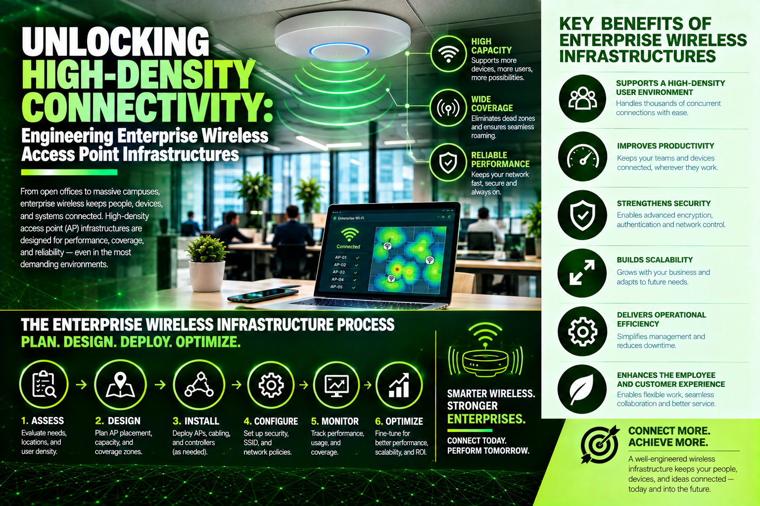
Unlocking High-Density Connectivity: Engineering Enterprise Wireless Access Point Infrastructures
Treating enterprise Wireless Access Points like plug-and-play consumer routers is a direct path to co-channel interference, coverage dead zones, and dropped connections. Dive into our comprehensive technical guide exploring Wi-Fi 6E and Wi-Fi 7 Multi-Link Operation (MLO), predictive RF site surveys, dual Category 6A cabling runs, and high-wattage PoE++ power budgets. Learn how Volthound Technologies provides on-site RF testing, multi-gigabit structured cabling, and Level VI certification to ensure your wireless network delivers seamless roaming and high-density performance across every square foot of your facility.
In the era of hybrid work, mobile workflows, IoT sensor expansion, and cloud-native operations, Wi-Fi is no longer just a convenience—it is mission-critical utility infrastructure. When an enterprise wireless network drops connections, experiences high latency, or suffocates under client density, business operations grind to a immediate halt. Employees lose access to cloud applications, handheld warehouse scanners disconnect mid-inventory, and guest networks collapse during high-stakes presentations.
Yet, many organizations still treat Wireless Access Points (WAPs) like consumer plug-and-play appliances. Mounting an enterprise access point on a wall and relying on default automatic channel settings is a recipe for coverage dead zones, co-channel interference, and poor user roaming. Delivering seamless, high-throughput wireless coverage across commercial spaces requires rigorous low-voltage planning, predictive radio frequency (RF) site surveys, structured Category 6A cabling, and precise physical placement.
The Engineering Realities of Modern Wi-Fi Standards
Deploying an enterprise wireless network requires understanding how evolving Wi-Fi protocols interact with physical building environments.
Wi-Fi 6 and 6E (802.11ax)
Wi-Fi 6 introduced key technologies such as OFDMA (Orthogonal Frequency-Division Multiple Access) and MU-MIMO (Multi-User, Multiple-Input, Multiple-Output), which allow access points to communicate with dozens of client devices simultaneously rather than sequentially. Wi-Fi 6E expanded this capability into the newly opened, uncrowded 6 GHz spectrum band, providing ultra-wide channels and near-zero legacy interference.
Wi-Fi 7 (802.11be)
Wi-Fi 7 represents a massive leap in wireless performance, offering Multi-Link Operation (MLO). MLO allows a single client device to transmit and receive data across multiple frequency bands (2.4 GHz, 5 GHz, and 6 GHz) concurrently. This dramatically reduces latency, increases throughput up to 46 Gbps theoretically, and provides seamless failover if one band experiences physical interference.
The Higher Frequency Trade-Off
While 5 GHz and 6 GHz bands deliver blistering data speeds, higher frequencies struggle to penetrate physical obstacles. Standard drywall, concrete pillars, glass partitions, and metal ductwork absorb or reflect 5 GHz and 6 GHz signals far more aggressively than legacy 2.4 GHz waves. Consequently, modern high-performance wireless designs require higher access point density and precise physical placement to prevent coverage shadows.
The Four Pillars of Enterprise Wireless Deployment
Designing a reliable enterprise wireless footprint involves four interdependent physical and technical phases.
1. Predictive and On-Site RF Site Surveys
Before pulling a single cable, network engineers must perform a Radio Frequency (RF) site survey. Using specialized software and floor plan CAD files, engineers model wall attenuation factors, floor materials, and ceiling heights to generate predictive signal heatmaps.
For complex environments—such as manufacturing plants, high-density warehouses with steel racking, or medical facilities—an active "AP-on-a-Stick" survey is required. Engineers temporarily mount an access point on a tripod at the exact planned elevation, measure real-world signal propagation, and identify physical RF blind spots before permanent installation.
2. High-Power PoE++ and Multi-Gigabit Switching
Modern Wi-Fi 6E and Wi-Fi 7 access points feature 2.5 Gbps or 5 Gbps Ethernet uplinks to prevent the physical cable link from becoming a bottleneck for multi-gigabit wireless traffic. Furthermore, advanced multi-radio APs demand high-wattage Power over Ethernet (PoE+ 802.3at or PoE++ 802.3bt) to operate all spatial streams and heating elements simultaneously.
If the underlying network switch closet lacks Multi-Gigabit (mGig) ports or adequate PoE power budgets, access points will operate in degraded, low-performance power profiles or fail to boot entirely.
3. Dual Category 6A Structured Cabling Drops
Enterprise wireless best practices dictate running two dedicated Category 6A plenum-rated copper drops to every access point location. Running dual drops provides two critical advantages:
Link Aggregation and Throughput: Combining two copper lines provides up to 10 Gbps of physical backhaul bandwidth to the switch closet while delivering redundant power paths.
Future-Proofing: Having a secondary spare drop at ceiling locations allows easy installation of secondary sensors, security cameras, or future wireless hardware iterations without needing expensive secondary cable pulls through ceiling spaces.
4. Strategic Physical Mounting and Aesthetic Integration
Access points are engineered to project RF signals outward and downward in specific omnidirectional or directional patterns. Mounting an access point vertically on a wall when it was designed for horizontal ceiling placement distorts the signal pattern, sending coverage into the ceiling plenum while creating dead zones on the floor.
Proper installation requires ceiling grid T-bar brackets, seismic safety wire ties, and wall-mount elevation brackets when dealing with open-structure industrial ceilings.
How Volthound Technologies Streamlines Wireless Deployments
Deploying enterprise wireless access points across multi-floor corporate offices, retail spaces, or industrial warehouses requires technical field execution. Volthound Technologies provides complete smart-hands services—bridging the gap between high-level RF software design and physical jobsite installation.
Volthound approaches wireless infrastructure with disciplined field methodology:
Comprehensive Predictive RF Modeling & On-Site Surveys: Volthound field technicians perform detailed predictive RF heatmap modeling and active on-site surveys. We evaluate building attenuation, identify sources of non-Wi-Fi interference (such as microwave equipment or Bluetooth arrays), and determine exact AP count and placement.
Multi-Gigabit Cabling & High-Power PoE Infrastructure: Volthound installs solid-copper, plenum-rated Cat6A drops engineered to support Multi-Gigabit (2.5G/5G) speeds and 802.3bt PoE++ power delivery, ensuring your switch infrastructure seamlessly feeds high-performance access points.
Precision Ceiling Mounting & Hardware Staging: Our technicians mount access points at precise calculated elevations using manufacturer-approved brackets, ensuring correct antenna orientation and clean cable concealment.
Level VI Certification and Channel Validation: Volthound tests and certifies every copper drop with Level VI cable analyzers, verifies PoE voltage under full load, configures channel assignments, and validates signal coverage against client SLA metrics.
ANSI/TIA Standardized Labeling & As-Built Documentation: Every drop, patch panel port, and AP is clearly labeled according to ANSI/TIA-606-C standards. Volthound delivers complete closeout packages—including validated post-installation RF heatmaps, port mapping schedules, and high-resolution photo documentation.
By combining RF engineering principles with disciplined low-voltage installation practices, Volthound Technologies ensures your wireless infrastructure delivers seamless roaming, high density, and rock-solid reliability across every square foot of your facility.
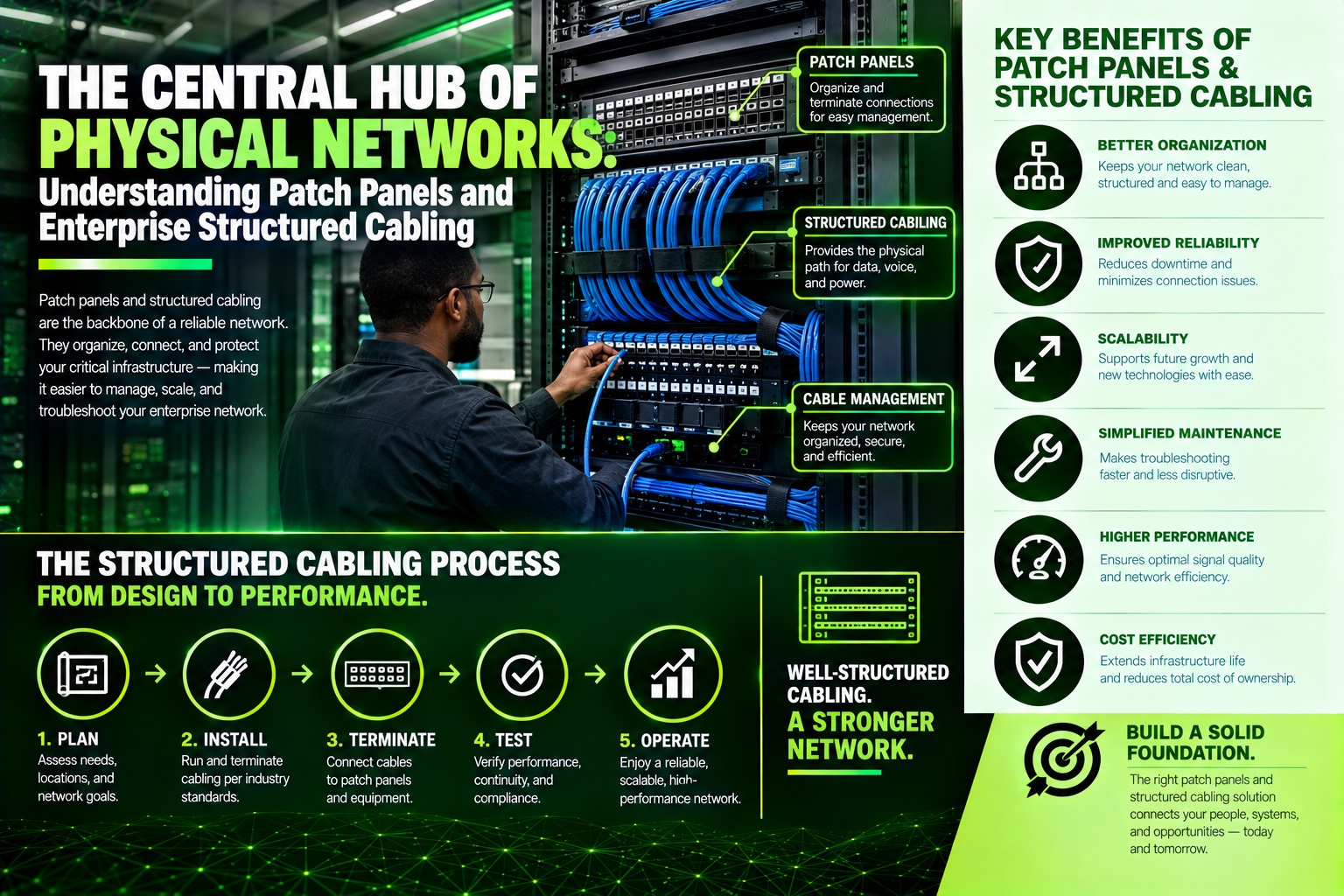
The Central Hub of Physical Networks: Understanding Patch Panels and Enterprise Structured Cabling
Blinking core switches get all the attention, but the patch panel is the true operational hub of any telecommunications closet. Serving as the permanent termination point for in-wall cabling, a properly engineered patch panel protects expensive hardware ports, prevents solid-core cable fatigue, and streamlines network troubleshooting. Read our technical guide exploring punch-down vs. modular keystone panels, shielded termination techniques, and ANSI/TIA-606-C labeling standards—and learn how Volthound Technologies delivers certified, neatly dressed patch field installations for maximum uptime.
When stepping into a server room or telecommunications closet, it is easy to focus on blinking switches, core routers, and high-density servers. However, behind those active network devices sits a critical piece of hardware responsible for keeping physical infrastructure organized: the patch panel.
A patch panel serves as the central termination assembly for all permanent, horizontal network cabling running through walls, ceilings, and conduit pathways. By separating permanent cabling from temporary patch cords, patch panels protect expensive hardware ports, streamline troubleshooting, and make network reconfigurations effortless.
The Engineering Role of Patch Panels in Network Architecture
Without a patch panel, Ethernet cables running from office desks, Wi-Fi access points, and security cameras would have to plug directly into switch ports. This direct-connection approach introduces severe operational liabilities:
1. Equipment Port Protection and Wear Reduction
Active network switches are expensive investments. Constantly plugging, unplugging, or moving direct cable runs wears down the spring-loaded RJ45 contacts on switch ports over time.
A patch panel acts as a sacrificial buffer. Permanent in-wall cabling terminates into the back of the patch panel (using Insulation Displacement Connectors, or IDCs). Day-to-day changes happen exclusively on the front of the panel using short, inexpensive patch cords. If a patch cord or RJ45 connector degrades, it can be replaced for a few dollars without damaging switch hardware or disturbing permanent in-wall wiring.
2. Elimination of Physical Strain on Permanent Cabling
Solid-core copper cables used for in-wall horizontal runs (such as Cat6 and Cat6A) are engineered for static installation, not frequent flexing. Bending or moving solid-core cables causes internal wire fatigue and broken conductors. Patch panels keep permanent runs fixed securely in place, while stranded-copper patch cords handle the physical flexibility required inside server racks.
3. Rapid Troubleshooting and Fault Isolation
When a workstation loses connectivity, tracing an unlabeled cable through a tangled web of wires can take hours. Patch panels consolidate all terminations into neatly numbered, color-coded, and standardized fields. IT administrators can instantly match a wall-plate outlet number to a specific patch panel port, test the line with a cable analyzer, and isolate issues to either the horizontal drop, the patch cord, or the switch port in seconds.
Exploring Patch Panel Architecture and Categories
Selecting the right patch panel configuration depends on bandwidth requirements, media types, and environmental factors.
Loaded Punch-Down vs. Modular Keystone Panels
Punch-Down Patch Panels: Traditional patch panels feature fixed rows of Insulation Displacement Connectors (IDCs) on the rear board. Technicians use a punch-down tool to seat individual copper wire pairs into 110-block or Kron-style terminals.
Modular Keystone Panels: Modern installations increasingly favor blank keystone patch panels. These frames allow technicians to snap individual, pre-terminated keystone jacks (RJ45 Cat6/6A, fiber optic couplers, or HDMI modules) directly into the panel. Modular panels offer unmatched flexibility, allowing mixed-media connections and easy replacement of individual damaged ports without replacing the entire panel.
Unshielded (UTP) vs. Shielded (FTP/STP) Panels
In environments with heavy electromagnetic interference (EMI)—such as manufacturing floors, medical imaging facilities, or locations where data cables run adjacent to high-voltage electrical lines—shielded patch panels are essential. Shielded panels feature metallic housings and dedicated grounding busbars that bond cable shielding to the building ground, preventing external electrical noise from compromising data rates.
Fiber Optic Enclosures and Cassettes
For high-speed backbone connections between MDFs and IDFs, fiber patch panels (or fiber enclosures) utilize LC, SC, or MTP/MPO adapters. These enclosures manage fiber bend radii, protect delicate fusion splices, and hold fiber cassettes that split high-density trunk cables into individual high-speed links.
How Volthound Technologies Streamlines Patch Panel and Cabling Deployments
Installing, dressing, terminating, and documenting hundreds of patch panel ports across multi-floor commercial facilities requires technical field capabilities. Volthound Technologies provides specialized smart-hands execution to ensure physical patch fields are engineered for long-term performance, clean aesthetics, and easy operation.
Volthound approaches patch panel buildouts with disciplined methodology:
Precision Termination Standards: Volthound field technicians adhere strictly to ANSI/TIA termination standards (T568B or T568A). We maintain minimal wire pair untwisting at termination points to minimize Near-End Crosstalk (NEXT) and keep signal loss to a minimum.
Clean Wire Dressing and Airflow Management: Disorganized "spaghetti cabling" blocks airflow, leading to server rack thermal issues. Volthound utilizes horizontal and vertical cable managers, rear cable support bars, and reusable hook-and-loop straps (eliminating sharp zip ties) to keep patch bays organized and ventilated.
ANSI/TIA-606-C Standardized Labeling: Volthound labels every patch panel port, faceplate, and cable drop using durable, machine-printed, color-coded labeling according to ANSI/TIA-606-C standards. This clear identification eliminates guesswork for future maintenance and IT audits.
Level VI Certification and Trace Reports: Volthound does not rely on simple continuity light checks. Every terminated port undergoes rigorous Level VI field certification to measure return loss, NEXT, cable length, and attenuation, delivering full trace reports to verify that lines meet or exceed Category specifications.
As-Built Documentation and CMDB Integration: Upon completion, Volthound provides complete closeout documentation—including rack elevation diagrams, port mapping schedules, and high-resolution photo documentation—ensuring your internal IT team has an accurate system of record.
By combining deep low-voltage cabling knowledge with disciplined field installation practices, Volthound Technologies ensures that your patch panel infrastructure serves as a reliable, high-speed foundation for your entire corporate network.
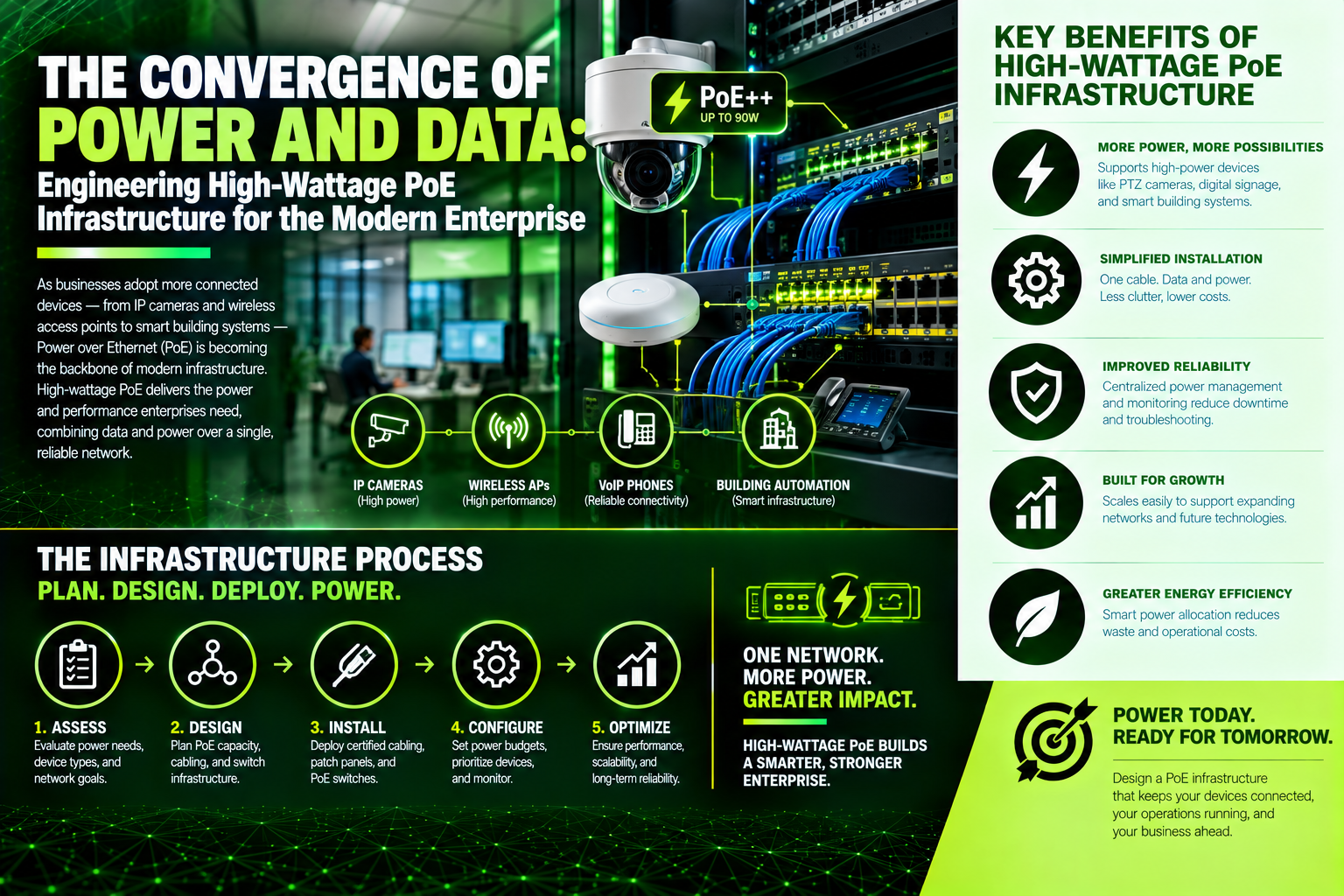
The Convergence of Power and Data: Engineering High-Wattage PoE Infrastructure for the Modern Enterprise
Power over Ethernet has transformed from a convenience for desk phones into a primary low-voltage power backbone delivering up to 90W over Category 6A cabling. However, running high-wattage DC power alongside high-speed data introduces serious physical challenges, including cable bundle self-heating, Direct Current Resistance Unbalance (DCRU), and connector arcing. Dive into our technical guide exploring IEEE 802.3bt standards, thermal mitigation strategies, and power budget calculations—and learn how Volthound Technologies delivers certified Cat6A installations, thermal-aware pathway design, and Level VI field validation.
In modern smart buildings, corporate offices, and industrial facilities, Power over Ethernet (PoE) has evolved from a convenience for desk phones into the primary power delivery backbone for entire physical environments. With a single Category 6 or Category 6A cable, enterprise networks now deliver high-speed data alongside operational DC power to Wi-Fi 7 access points, pan-tilt-zoom security cameras, smart access control, digital signage, and intelligent LED lighting.
Eliminating dedicated electrical conduits for low-voltage endpoints drastically reduces facility deployment costs and provides centralized power management. However, as PoE standards scale up to 90W and 100W per port under IEEE 802.3bt (Type 4 / PoE++), powering dozens of high-wattage devices over bundled copper introduces thermal, structural, and electrical challenges. Without proper low-voltage engineering, PoE installations suffer from voltage drops, cable bundle overheating, premature switch port failure, and intermittent network resets.
Understanding the Shift to High-Wattage PoE Standards
Deploying an enterprise PoE infrastructure requires an understanding of how power delivery standards dictate cable selection and switch architecture.
PoE (IEEE 802.3af - Type 1): Delivers up to 15.4 Watts of DC power at the switch port (12.95W at the device) using two pairs of twisted copper. This standard remains suitable for basic IP phones, static indoor cameras, and simple card readers.
PoE+ (IEEE 802.3at - Type 2): Increases power delivery to 30 Watts per port (25.5W at the device) over two pairs. PoE+ supports dual-band Wi-Fi 5/6 access points, motorized PTZ cameras, and video IP phones.
PoE++ (IEEE 802.3bt - Type 3 & Type 4): Utilizes all four pairs of the copper cable to deliver 60 Watts (Type 3) or up to 90–100 Watts (Type 4) per port. This high-power standard powers multi-radio Wi-Fi 7 access points, large-format digital menu boards, smart building automation controllers, and laptop docking stations.
Physical Engineering Challenges in High-Power PoE Environments
Passing high wattage through thin copper conductors creates physical realities that do not exist in standard data-only structured cabling plants.
1. Thermal Dissipation and Cable Bundle Self-Heating
When high-wattage current passes through copper conductors, resistance naturally generates heat. In tightly bound cable trays or ceiling pathways where dozens of 802.3bt lines are bundled together, this internal heat cannot easily escape. Higher cable temperatures increase DC resistance, which causes insertion loss (signal attenuation) to spike. If temperatures exceed cable jacket ratings, signal integrity degrades rapidly, and cable bundles become fire hazards. Managing bundle size limits and utilizing high-performance Category 6A shielded cabling are critical for dissipating thermal loads.
2. Direct Current Resistance Unbalance (DCRU)
High-power 4-pair PoE (802.3bt) splits current evenly across all four twisted pairs. If a cable has manufacturing defects, poor terminations, or bent conductors, current flows unevenly through the pairs. This Direct Current Resistance Unbalance (DCRU) saturates the magnetic transformers inside network switch ports, causing signal distortion, high bit-error rates, and unexpected device reboots.
3. Arcing on Disconnect
Unplugging an active high-wattage PoE cable while current is flowing creates a physical electrical arc across the RJ45 connector pins. Over time, repeated hot-unplugging degrades and corrodes the gold plating on both patch cord plugs and switch ports, leading to permanent connection failures. Modern PoE switches require software-managed power turn-down before physical cable disconnection.
Power Budgeting and Redundancy Architecture
Building an enterprise PoE plant requires looking beyond individual port limits to calculate total Power Sourcing Equipment (PSE) capacity.
Switch Power Budgeting: A 48-port switch supporting 802.3bt cannot deliver 90W on every port simultaneously without an enormous power supply. IT teams must calculate real-world device draw versus nominal peak wattage to avoid over-subscribing switch power supplies.
Uninterruptible Power Supply (UPS) Sizing: Because PoE powers critical safety systems—including IP security cameras, access control doors, and emergency Wi-Fi—the central MDF/IDF battery backups must be sized to support both the network switch processing load and the connected PoE devices during utility power outages.
Midspan Injectors vs. Endspan Switches: While upgrading to full PoE++ switches is ideal, deploying high-density midspan power injectors offers a cost-effective way to add high-wattage 802.3bt ports to existing switch plants without replacing core network hardware.
How Volthound Technologies Optimizes Enterprise PoE Deployments
Designing, testing, and deploying high-wattage Power over Ethernet systems requires specialized low-voltage capabilities. Volthound Technologies provides complete field services to ensure your physical network layer supports high-power PoE safely and reliably.
Volthound approaches PoE infrastructure with disciplined field execution:
Thermal-Aware Pathway Design & Bundle Sizing: Volthound field technicians design overhead pathway layouts that respect maximum cable bundle thresholds, ensuring proper airflow and thermal dissipation for high-density 802.3bt deployments.
Category 6A Shielded Cabling & Precision Termination: Volthound installs solid-copper, plenum-rated Cat6A shielded drops. Our technicians follow strict termination protocols to eliminate DC Resistance Unbalance and protect sensitive switch electronics.
PoE Field Validation & DC Resistance Testing: Using advanced Level VI cable analyzers, Volthound tests every line for continuity, bandwidth, DCRU, and thermal rise under active load, delivering full certification reports before devices go live.
Power Budget Audit & UPS Integration: Volthound evaluates total switch power budgets, configures PoE port priority profiles, and sizes IDF battery backup systems to guarantee continuous operation during power emergencies.
Labeling, Mapping, and As-Built Documentation: Every drop, patch panel port, and switch interface is clearly labeled according to ANSI/TIA standards, accompanied by detailed closeout packages for seamless ongoing management.
By combining low-voltage engineering knowledge with rigorous field testing, Volthound Technologies transforms complex PoE requirements into clean, safe, and reliable infrastructure realities.
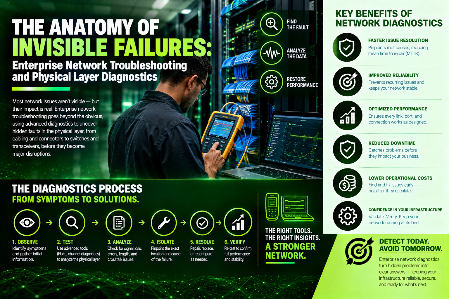
The Anatomy of Invisible Failures: Enterprise Network Troubleshooting and Physical Layer Diagnostics
When enterprise networks experience mystery packet loss, high latency, or sudden dropouts, software configuration isn't always to blame—over half of all persistent network failures stem directly from Layer 1 physical issues. Read our technical guide exploring copper crosstalk dynamics, fiber end-face contamination, and thermal PoE overloading. Discover how Volthound Technologies provides Level VI cable certification, OTDR fiber testing, and on-site smart-hands troubleshooting to eliminate physical network bottlenecks permanently.
When an enterprise network experiences intermittent packet loss, high latency, or sudden dropouts, the immediate instinct for many internal IT teams is to dive straight into software logs, firewall policies, or cloud routing tables. Yet, industry data consistently demonstrates that over half of all persistent network anomalies originate not in software configurations, but within the physical layer—the unseen web of copper patch drops, fiber optic trunks, patch panel terminations, and environmental factors inside network closets.
When physical layer issues are misdiagnosed as software bugs, companies lose dozens of hours in diagnostic wild-goose chases. Developing a structured, systematic approach to network troubleshooting is essential for restoring operational stability and maintaining enterprise uptime.
The Root Causes of Physical and Low-Voltage Network Degradation
To effectively diagnose network degradation, network engineers must look beyond high-level dashboard status lights and understand the physical phenomena that disrupt bit transmission.
1. Copper Infrastructure and Crosstalk Dynamics
In twisted-pair Ethernet cables (such as Category 6 and Category 6A), data relies on precise electrical differential signaling across four pairs of copper wire. When cables are improperly pulled, pinched around tight corners, or bundled with heavy plastic cable ties, the geometric symmetry of these wire pairs is compromised.
This geometric distortion creates Alien Crosstalk (AXT) and Near-End Crosstalk (NEXT), where electrical signals jump between adjacent wire pairs or neighboring cables within a bundle. While a cable may pass a basic continuity test, high-frequency data transmission will suffer severe frame errors, forcing switch ports to drop down to lower speeds or repeatedly retransmit dropped packets.
2. Optical Fiber Contamination and Micro-Bending
Fiber optic backbones carry light pulses across glass cores as small as 8.3 microns in single-mode runs. The most common cause of fiber link failure is invisible contamination—microscopic dust particles, oils, or skin residues deposited on connector end-faces during patch panel insertion.
A dust particle smaller than a human red blood cell can block the light path entirely or cause significant optical reflection back toward the transmitter (High Return Loss). Furthermore, exceeding a fiber cable’s minimum bend radius causes micro-bending loss, where light escapes through the cladding of the glass strand, causing signal attenuation and mysterious, time-of-day dropouts as temperature fluctuations shift structural pressures.
3. Thermal Throttling and Power over Ethernet (PoE) Saturation
Modern networks rely heavily on Power over Ethernet (PoE+ and PoE++) to power access points, security cameras, and smart building sensors directly over data cables. Passing up to 90 Watts of power through dense bundles of unshielded copper generates internal heat.
If structured cabling pathways lack adequate ventilation or exceed maximum bundle size guidelines, the heat buildup increases electrical resistance. This higher resistance degrades signal distance limits, causes voltage drops to remote endpoints, and can even cause switch ports to shut down automatically to prevent thermal damage.
A Systematic Framework for Network Isolation
Rather than guessing at root causes, effective field troubleshooting follows a disciplined, layered methodology that systematically isolates variables from physical layer to application layer.
Step 1: Physical Inspection and Cable Health Certification
Troubleshooting should always begin at Layer 1. Technicians physically inspect patch cords for kinked jackets, verify proper bend radii along ladder racks, check for loose modular plugs, and run Level VI field certification tests on suspect copper drops. For fiber backbones, optical power meters and Optical Time-Domain Reflectometers (OTDRs) trace the precise distance to any point of light loss or cable damage.
Step 2: Link State and Physical Port Verification
Once physical lines are verified, engineers analyze the switch port operational status. Checking port status registers reveals auto-negotiation mismatches (such as one end running Full-Duplex while the other operates in Half-Duplex), Cyclic Redundancy Check (CRC) error counters, and jabber frames. High CRC error counts strongly indicate physical interference or bad cable terminations rather than software routing bugs.
Step 3: Layer 2 Data Link and VLAN Mapping
With physical links confirmed clean, engineers verify Layer 2 operational parameters. This involves checking Virtual Local Area Network (VLAN) tagging, Spanning Tree Protocol (STP) topology states to detect switching loops, and Address Resolution Protocol (ARP) tables to ensure MAC addresses are properly learned across all intermediate switches.
Step 4: Layer 3 IP Routing and Transport Layer Validation
Finally, diagnostics move to IP routing and gateway reachability. Tools like Pathping, MTR (My Traceroute), and packet analyzers isolate latency spikes and packet loss to specific hop locations, distinguishing local internal infrastructure bottlenecks from external Internet Service Provider (ISP) transport failures.
How Volthound Technologies Streamlines Field Troubleshooting for Enterprise Clients
When network outages strike or chronic performance issues baffle internal IT staff, deploying dedicated field technicians provides rapid resolution without pulling internal engineering teams away from core business operations. Volthound Technologies provides specialized smart-hands diagnostics and field troubleshooting services to restore physical and low-voltage network health.
Volthound approaches complex network troubleshooting with deep field experience and specialized diagnostic equipment:
Comprehensive Layer 1 Field Certification: Volthound field technicians utilize industry-standard cable analyzers to test copper and fiber infrastructure. We measure Near-End Crosstalk (NEXT), Return Loss, Insertion Loss, and length, delivering definitive diagnostic reports that identify broken or degraded physical drops instantly.
Fiber End-Face Inspection and Fusion Repair: For optical backbone failures, Volthound uses digital inspection microscopes to detect end-face contamination and optical power meters to pinpoint light loss locations. Where broken strands or poor mechanical splices exist, our technicians perform precision core-alignment fusion splicing to restore optical links to factory specifications.
Pathway Audits and Cable Dressing Remediation: Volthound inspects overhead cable trays, ceiling pathways, and network closet wire management. We replace abrasive plastic ties with reusable hook-and-loop straps, resolve tight bend-radius violations, and eliminate disorganized "spaghetti cabling" that restricts airflow and causes thermal buildup.
Thermal Diagnostics and PoE Load Balancing: Technicians evaluate power distribution across switch stacks and PDUs, measuring environmental temperatures inside network closets and balancing PoE loads across switch cards to prevent thermal throttling and hardware shutdowns.
Complete System Documentation and As-Built Updates: Once issues are resolved, Volthound provides updated port mapping, clean labeling according to ANSI/TIA standards, and detailed closeout reports so your internal IT team maintains a accurate system of record for ongoing operations.
By combining low-voltage engineering knowledge with disciplined, tool-assisted field diagnostics, Volthound Technologies transforms frustrating network issues into clear, actionable, and permanent solutions.
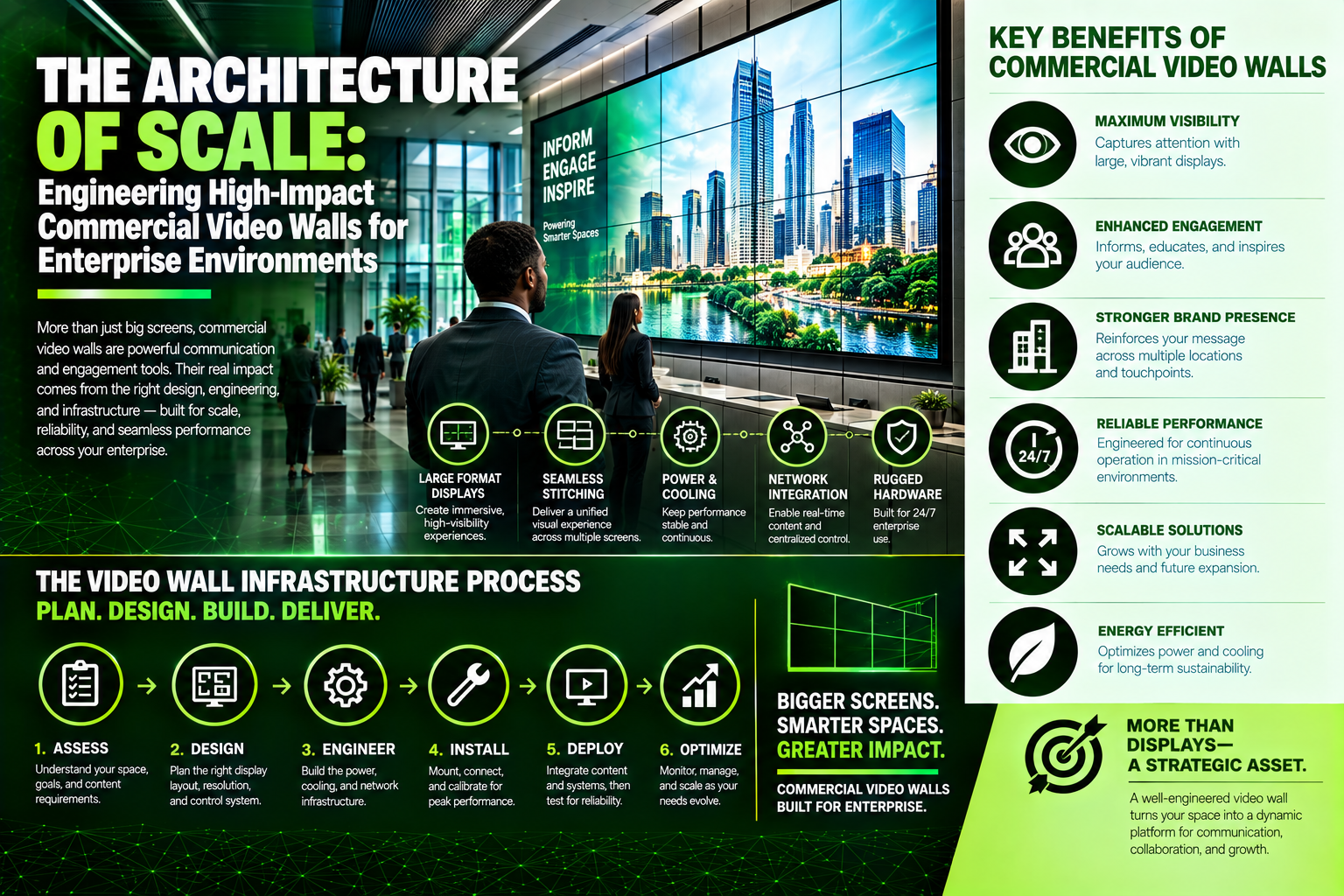
The Architecture of Scale: Engineering High-Impact Commercial Video Walls for Enterprise Environments
Installing an enterprise video wall requires far more than mounting screens side-by-side—it demands an engineering-first strategy. Explore our comprehensive technical guide comparing Direct View LED (DVLED) and tiled LCD arrays, detailing structural load distribution, pop-out mounting mechanics, thermal airflow management, and AV-over-IP signal processing. Discover how Volthound Technologies provides precision sub-framing, laser alignment, fiber backbone drops, and color calibration to deliver flawless video wall execution.
Large-format visual canvases have evolved from luxury architectural features into critical operational assets. In executive boardrooms, corporate lobbies, network operations centers, emergency response facilities, and high-end retail flagships, video walls serve as primary communication engines. They aggregate real-time telemetry, display high-resolution corporate messaging, facilitate global video collaboration, and immerse visitors in dynamic brand storytelling.
However, installing an enterprise video wall is one of the most physically and technically demanding projects in commercial AV integration. A video wall cannot be approached like a series of standalone monitors mounted adjacent to one another. Achieving a seamless, long-lasting installation requires rigorous engineering across structural framing, electrical distribution, low-voltage signal architecture, thermal management, and color calibration.
Tiled LCD vs. Direct View LED: Architectural Mechanics and Canvas Selection
Selecting the core display technology dictates every downstream physical requirement, from wall loading and electrical planning to thermal dissipation and processing hardware.
1. Extreme-Narrow Bezel (ENB) and Ultra-Narrow Bezel (UNB) Tiled LCD Arrays
Tiled LCD video walls consist of commercial-grade liquid crystal displays arranged in grid formations (such as 2x2, 3x3, or 5x5). Modern commercial LCD panels feature sub-millimeter bezels, resulting in total combined seam widths as thin as 0.88 millimeters.
LCD arrays excel in control room environments, such as security operation centers (SOCs) and industrial command centers, where operators read fine text, detailed schematics, and high-density data feeds from close range. Because each panel provides native 1080p or 4K resolution, a tiled array generates immense pixel density. However, LCD panels possess physical borders, meaning grid seam lines will always remain slightly visible. Furthermore, LCD panels exhibit viewing angle variations and require precise multi-panel backplane alignment to prevent uneven depth between adjacent screens.
2. Direct View LED (DVLED) Modular Canvases
Direct View LED technology eliminates display bezels entirely, creating a uninterrupted, seamless visual canvas. DVLED walls are constructed using small, modular cabinets that snap together, housing matrix arrays of surface-mounted light-emitting diodes (SMDs or MicroLEDs).
DVLED selection is governed primarily by pixel pitch—the center-to-center distance between adjacent LED pixels measured in millimeters. For indoor enterprise applications, pixel pitches typically range from ultra-fine 0.9mm up to 2.5mm. The lower the pixel pitch, the closer a viewer can stand without perceiving individual light points, though smaller pitch values significantly increase hardware density and cost.
DVLED offers brightness capabilities ranging from 800 nits to over 2,000 nits, along with deep black levels and wide viewing angles. This makes DVLED ideal for sunlit corporate lobbies, glass-walled atriums, and high-impact executive presentation spaces. However, DVLED installations require precise physical alignment tolerances; a deviation of a fraction of a millimeter in sub-framing can cause visible dark or bright seam lines across the LED module joints.
Physical and Infrastructure Engineering for Video Wall Deployments
Behind the visual display lies a complex network of physical infrastructure. Skimping on background structural or low-voltage planning frequently results in structural sag, overheating, signal drops, and unserviceable hardware.
1. Structural Load Distribution and Micro-Adjustable Mounts
A large video wall array generates substantial static and cantilevered weight on building structures. A 3x3 array of 55-inch commercial LCD displays, including mounting hardware, can easily exceed 600 pounds, while large-format DVLED walls can weigh thousands of pounds. Mounting directly to standard drywall with simple wall anchors is impossible and dangerous.
Engineered buildouts require structural wall reinforcement—such as continuous three-quarter-inch fire-rated plywood backing anchored securely across heavy-gauge steel studs, or direct mechanical ties to structural concrete or structural steel framework.
For LCD arrays, specialized pop-out mounting brackets with micro-adjustments along x, y, and z axes are mandatory. These brackets allow technicians to extend an individual interior display forward out of the matrix for servicing without disturbing surrounding panels, while precise depth and height adjustments ensure all panel faces sit completely flush. For DVLED, rigid extruded aluminum mounting frames must be laser-leveled across the entire wall surface to ensure the LED cabinet alignment pins engage without mechanical stress.
2. Thermal Management and Dedicated Power Architecture
Video wall electronics generate heat. Operating dozens of high-brightness LCD backlights or thousands of LED diodes within a tight wall cavity creates thermal buildup. Excessive heat degrades LED lifespan, causes color shifting across panels, and leads to premature power supply failure.
Engineering a video wall requires calculating thermal dissipation metrics and providing dedicated airflow channels. In enclosed or recessed wall cavities, low-noise active ventilation fans or connection to the building’s HVAC system must be integrated behind the display plane.
Power distribution must also be calculated. High-density display arrays draw significant amperage, especially during initial power-on inrush current. Dedicated electrical circuits, managed power distribution units (PDUs) with sequential power-on sequencing, and remote power supplies (which place heavy power transformers in a remote server closet rather than behind the hot display wall) keep thermal loads down and simplify ongoing maintenance.
3. Signal Transport and Processing: Video Wall Controllers and AVoIP
Delivering content across a multi-panel display requires dedicated video wall processing. Standard media players or computers cannot natively map video sources across non-standard resolutions or multi-screen matrix layouts without scaling distortion.
Dedicated Video Wall Processors: Hardware-based video processors utilize high-bandwidth backplanes to capture multiple physical inputs (such as PC feeds, media players, streaming cameras, and video conferencing systems) and scale them dynamically across user-defined windows or full-canvas layouts with sub-frame latency.
AV-over-IP (Audio-Visual over IP) Matrix Networks: Modern video wall deployments increasingly utilize AV-over-IP architectures. High-resolution encoders convert video sources into network streams distributed over managed 10GbE copper or fiber network switches. Decoders positioned behind each display panel or DVLED controller receive these streams and stitch the master canvas together via software. AV-over-IP offers unlimited expansion, allowing any source across an entire corporate network to be routed to any display or sub-section of the video wall instantly.
How Volthound Technologies Streamlines Complex Video Wall Deployments
Executing an enterprise video wall project requires specialized field technical capabilities. Volthound Technologies provides end-to-end field services—bridging the gap between AV system design and physical jobsite execution.
Volthound supports enterprise clients, general contractors, and AV system integrators through a hands-on methodology:
Pre-Installation Site Surveys and Structural Audits: Before any equipment arrives, Volthound field technicians perform on-site evaluations. They verify wall load capacities, measure floor-to-ceiling tolerances, inspect high-voltage electrical drops, evaluate ambient lighting conditions, and trace low-voltage cable pathways to prevent jobsite delays.
Precision Sub-Framing and Mount Installation: Volthound handles the heavy mechanical assembly. Technicians install heavy-duty aluminum mounting tracks and pop-out frames using precision laser levels and micro-adjustment procedures, ensuring the sub-structure is plumb and level to within fractions of a millimeter.
Structured Cabling and Fiber Backbone Drops: Volthound pulls plenum-rated Category 6A copper runs and multi-strand optical fiber backbones from network closets directly to display wall cavities. Technicians terminate, dress, and test every line to guarantee full, uncompressed bandwidth transmission without signal loss.
Hardware Staging, Video Processor Enrollment, and AVoIP Configuration: Field technicians mount display cabinets, configure video processors and AVoIP decoders, assign static IP addresses, and program canvas resolution layouts to align with client operational requirements.
Color Calibration, Thermal Validation, and As-Built Closeout: Every Volthound deployment finishes with physical testing—including panel color and brightness uniformity calibration using optical spectrophotometers, thermal clearance inspections, and the delivery of complete closeout documentation with as-built wiring diagrams and high-resolution photo records.
By combining low-voltage engineering knowledge with disciplined field execution standards, Volthound Technologies ensures your video wall investment delivers visual impact, operational reliability, and maximum uptime.

The Digital Menu Revolution: Engineering Dynamic Service Boards for Modern Retail and Commercial Spaces
Static printed menu boards are a bottleneck for modern retail, food service, and commercial service centers. Transitioning to dynamic digital service menu boards enables real-time POS integration, automated dayparting, and centralized price updates across all your locations. Explore our comprehensive technical guide covering commercial display selection, high-ambient brightness, micro-adjustable array mounting, and structured cabling—and learn how Volthound Technologies delivers seamless on-site field execution and CMS enrollment.
Static printed posters and acrylic menu boards are no longer sufficient in fast-paced retail, food service, automotive, healthcare, and commercial service environments. Relying on physical signage imposes severe operational friction: changing a price, adding a service tier, or promoting a seasonal campaign requires expensive redesigns, reprinting delays, and manual installation across every location. This slow turnaround directly limits agility and leads to inconsistent pricing across regional sites.
Transitioning to commercial digital service menu boards converts static walls into dynamic, real-time communication platforms. A modern digital menu board array allows corporate teams to adjust pricing globally in seconds, schedule automated dayparting promotions, highlight high-margin service upsells through subtle video motion, and sync display data directly with cloud-based Point-of-Sale (POS) and Enterprise Resource Planning (ERP) databases.
However, deploying an enterprise-grade digital menu board array involves far more than mounting standard televisions on a wall and plugging in a USB flash drive. Building a reliable, eye-catching menu board system requires careful engineering—incorporating high-brightness commercial displays, heavy-duty structural mounting, dedicated low-voltage data infrastructure, and centralized Content Management System (CMS) network enrollment.
Technical Engineering: Commercial Menu Displays versus Consumer Screens
A common pitfall in digital menu deployments is choosing low-cost consumer televisions over industrial commercial displays. While consumer screens appear cost-effective initially, their underlying engineering is unsuited for the demanding environments of commercial service areas.
1. Continuous Operational Duty Cycles and Thermal Dissipation
Service menu boards typically operate continuously for 12 to 24 hours per day under heavy ambient lighting and warm commercial kitchen or retail conditions. Consumer TVs are built for intermittent residential usage (4 to 8 hours daily) in cool rooms. When subjected to continuous commercial operation, heat accumulates behind the display glass, cooking the internal power supply, drying out capacitor electrolyte, and causing permanent panel discoloration or backlight "burn-in."
Commercial-grade menu displays feature industrial circuit boards, active heat sinks, and metal chassis designed for rapid thermal dissipation. They are explicitly rated for continuous 16/7 or 24/7 duty cycles, ensuring uniform color accuracy and backlight longevity over years of continuous operation.
2. High Ambient Brightness and Anti-Glare Panel Coatings
Service counter environments are frequently washed in bright overhead fluorescent or LED lighting, and many feature large glass storefronts. Standard consumer televisions generate only 250 to 350 nits of brightness, causing ambient light to turn the glass screen into a mirror that obscures service pricing.
Commercial displays designed for menu boards deliver 500 to 700+ nits of brightness. Combined with specialized matte, anti-reflective coatings, commercial panels scatter overhead light glare without washing out text or dimming vibrant promotional graphics, keeping pricing crisp and readable from across the customer queue.
3. Orientation Flexibility and Ultra-Narrow Bezel Alignment
Consumer TVs are built exclusively for horizontal orientation. Mounting a consumer television vertically for a portrait menu board distorts heat ventilation, creating thermal hot spots at the top of the unit that cause premature backlight failure. Furthermore, consumer TV bezels feature an asymmetrical lower lip designed for tabletop legs, which looks crooked and unbalanced when rotated into portrait mode.
Commercial panels feature symmetrical bezels on all four sides and internal cooling pathways designed to operate seamlessly in both landscape and portrait orientations. Additionally, commercial panels designed for multi-screen menu walls feature ultra-narrow bezels—sometimes under 1.8 millimeters—ensuring that text and graphics spanning multiple displays appear contiguous without distracting gaps.
Infrastructure Requirements for Digital Menu Deployments
A reliable digital menu board network relies on robust structural, electrical, and data infrastructure hidden behind the displays.
1. Structural Backing and Precision Micro-Adjustable Mounts
Multi-display menu arrays (frequently three to six screens mounted in a continuous row) exert considerable weight and leverage on wall structures. Mounting display arrays directly into standard drywall using basic wall anchors is a major safety risk. Professional installations require solid structural backing—such as three-quarter-inch plywood blocking installed behind drywall—or direct mechanical anchoring into structural steel studs or concrete.
Furthermore, mounting multi-screen arrays requires commercial wall tracks with micro-adjustable mounting arms. These specialized brackets allow installers to finely adjust the height, depth, and tilt of each individual panel along x, y, and z axes. Without micro-adjustment controls, minor wall variations create uneven display seams, ruining the seamless look of the display array.
2. Concealed Power and Low-Voltage Cabling
Visible wires, hanging power cables, or exposed media players severely degrade the professional look of a customer-facing service area. Installations require recessed in-wall junction boxes situated directly behind the display brackets. These boxes contain line-voltage outlets, surge suppressors, and cable pass-throughs to conceal all wiring behind the screen chassis.
Data connectivity is equally crucial. While consumer devices rely on Wi-Fi, commercial digital signage networks require hardwired Category 6 or 6A copper Ethernet drops connected directly to an Intermediate Distribution Frame (IDF). A wired network link guarantees that media players receive instant pricing updates and content updates from the CMS without dropping connections due to wireless interference in crowded retail spaces.
3. External Media Players and Thermal Enclosures
High-reliability digital menu board systems utilize external commercial media players (such as BrightSign or specialized industrial PCs) mounted securely behind the displays. Placing media players inside ventilated, lockable rear enclosures protects the hardware from dust, grease, and accidental physical tampering while ensuring easy technician access for service without unmounting the heavy display panels.
How Volthound Technologies Streamlines Menu Board Deployments
Deploying digital service menu board networks across single locations or multi-site commercial chains requires experienced field execution. Volthound Technologies provides comprehensive field installation services—bridging the gap between software platforms and physical jobsite execution.
Volthound supports enterprise clients, retail chains, and signage platform providers through a disciplined, hands-on methodology:
Pre-Installation Site Surveys and Pathway Audits: Volthound field technicians perform thorough on-site evaluations before hardware arrives. They check wall construction, verify structural load ratings, assess ambient light angles, confirm power placement, and inspect low-voltage cable pathways to prevent jobsite delays.
Precision Structural Mounting and Array Laser Alignment: Volthound manages all structural mounting tasks. Technicians install heavy-duty multi-display wall tracks and suspension rigs, utilizing precision laser levels and micro-adjustable mounts to eliminate seams and create a clean, single-canvas look across multi-panel menu arrays.
Structured Cabling and Network Infrastructure: Volthound pulls plenum-rated Cat6 or Cat6A drops from local network closets directly to the display array. Technicians neatly terminate, test, and label every line, delivering dedicated, high-speed wired connectivity for real-time POS and CMS synchronization.
Media Player Staging, Configuration, and CMS Enrollment: Volthound field technicians handle device configuration and mounting. They install media players in rear-mount enclosures, configure IP network settings, pair devices with your chosen Content Management System, and verify resolution, frame rates, and display schedules across all screens.
System Testing, Calibration, and As-Built Closeout: Every Volthound project ends with thorough system validation—including panel brightness and color calibration checks, thermal clearance verification, and the delivery of complete closeout documentation with high-resolution photos and cable test reports.
By combining deep technical knowledge of low-voltage AV routing with disciplined field execution, Volthound Technologies ensures your digital service menu boards deliver maximum visual impact, absolute operational reliability, and long-term return on investment.

Beyond the Screen: Engineering Commercial Display Infrastructure for Enterprise Performance
Installing a consumer TV in a commercial space is a fast track to panel burnout, voided warranties, and unmanageable screens. Explore our technical guide on commercial display infrastructure—from duty cycles, 2,500+ nit brightness, and anti-glare coatings to structural mounting, HDBaseT, and AV-over-IP signal distribution. Learn how Volthound Technologies provides on-site field execution, precision mounting, and CMS enrollment to bring your visual communications to life.
Digital displays have transformed from simple decorative accessories into mission-critical operational tools. Across modern corporate headquarters, high-end retail footprints, healthcare facilities, and transportation hubs, commercial display technology drives employee collaboration, delivers real-time data, enhances guest experiences, and showcases dynamic brand messaging. From high-impact lobby video walls and interactive wayfinding kiosks to floor-wide digital signage networks, screens are the primary visual interface between organizations and their audiences.
However, treating commercial displays as mere plug-and-play televisions introduces significant financial and operational friction. Installing a consumer-grade TV in a commercial setting almost guarantees premature panel failure, severe image retention, voided warranties, and fragmented management. True enterprise display deployments require an engineering-first approach that integrates commercial-grade hardware, structural backing, thermal planning, structured cabling, and centralized media distribution.
Consumer TVs versus Commercial Panels: The Hardware Disconnect
At first glance, a 75-inch consumer television from a big-box retailer appears identical to a 75-inch commercial display, often at a lower initial purchase price. However, the internal architecture, thermal engineering, and display driver logic are fundamentally different.
1. Operational Duty Cycles and Thermal Management
Consumer televisions are designed for light residential usage—typically four to eight hours of non-continuous operation per day in climate-controlled living rooms. Their internal chassis rely on passive air movement and basic plastic enclosures. When operated continuously, heat builds up behind the liquid crystal layer, leading to backlight degradation, color shifting, permanent image retention (burn-in), and premature panel failure.
Commercial displays are engineered with industrial-grade circuit boards, heavy-duty metal backings, integrated heat sinks, and temperature sensor arrays. They are explicitly rated for continuous 16/7 or 24/7 operational cycles. Commercial panels dissipate thermal loads effectively, preserving color uniformity and backlight brightness over tens of thousands of operating hours.
2. High Brightness and Advanced Anti-Glare Coatings
Standard consumer TVs produce between 250 and 350 nits of brightness, designed for low-to-moderate indoor lighting. In sunlit corporate lobbies, glass-fronted storefronts, or brightly lit airport concourses, consumer screens become reflective mirrors, rendering content unreadable.
Commercial panels offer panel brightness levels ranging from 500 nits for standard indoor rooms to 2,500+ nits for window-facing and outdoor environments. Furthermore, commercial screens feature specialized anti-reflective, matte surface coatings that scatter ambient light without degrading image clarity or color saturation.
3. Remote Control, Automation, and Security
Consumer TVs depend almost entirely on infrared (IR) handheld remotes or consumer-grade smart TV applications. In a commercial environment, managing dozens of displays with individual remotes is impossible, and consumer smart OS platforms introduce serious cybersecurity vulnerabilities when connected to enterprise Wi-Fi networks.
Commercial displays omit consumer smart applications in favor of hardened system-on-chip (SoC) architectures or dedicated external media players. They feature robust industrial control interfaces, including RS-232 serial ports, Ethernet LAN control, and full compatibility with enterprise AV management platforms like Crestron, Extron, and Q-SYS. This allows network administrators to automate power schedules, lock out local buttons to prevent tampering, monitor display health metrics, and execute remote firmware updates across hundreds of screens simultaneously.
4. Orientation Versatility and Bezel Symmetry
Consumer televisions are built exclusively for horizontal (landscape) placement. Mounting a consumer TV vertically (portrait mode) causes heat to pool at the top edge of the panel, cooking internal power supplies and causing uneven backlight fading. Additionally, consumer TV bezels are asymmetrical, featuring a wider bottom lip designed for table stands, which looks visually unbalanced when rotated.
Commercial displays feature symmetrical bezels on all four sides and active cooling channels designed to operate seamlessly in both landscape and portrait orientations without thermal throttling or structural strain.
Physical Architecture of an Enterprise AV Buildout
A commercial display system is only as reliable as the physical infrastructure supporting it. A complete installation requires precision across three main disciplines: structural mounting, power planning, and signal distribution.
1. Structural Backing and Precision Mounting Mechanics
Large-format displays and multi-panel video walls exert substantial static and dynamic weight loads on building walls. Mounting directly into drywall with standard anchors is a severe safety hazard. Professional buildouts require structural wall backing—such as three-quarter-inch marine-grade plywood blocking installed behind the drywall during construction—or direct anchoring into heavy-gauge steel studs or masonry.
Furthermore, multi-screen video walls require specialized commercial mounting brackets featuring push-in/push-out service access and micro-adjustment knobs along x, y, and z axes. These adjustments allow field technicians to align panel bezels to fractions of a millimeter, creating a seamless visual canvas.
2. Low-Voltage Routing and Recessed Power
Visible wires and hanging power cords ruin the visual presentation of a professional display installation. Professional deployment requires recessed in-wall junction boxes positioned directly behind the display bracket. These enclosures house line-voltage power receptacles, surge protection devices, and low-voltage pass-throughs for structured copper or fiber lines.
Power routing must also comply with national electrical codes. Running flexible appliance cords or standard HDMI cables inside drywall without proper plenum ratings is a major code violation and fire hazard.
3. Signal Distribution: HDBaseT versus AV-over-IP
Delivering pristine 4K video from a centralized server rack to remote displays scattered across a building requires dedicated signal extension technology, as standard HDMI cables experience signal degradation beyond 15 feet.
HDBaseT: A point-to-point transport technology that carries uncompressed Ultra-HD video, digital audio, Ethernet, USB control, and power over a single Category 6A copper cable up to 100 meters (328 feet). HDBaseT is ideal for dedicated, fixed point-to-point runs, such as connecting a conference room table transmitter to a front-of-room display.
AV-over-IP (Audio-Video over Internet Protocol): Modern enterprise display networks increasingly utilize AV-over-IP. This architecture uses packet-based encoders and decoders to transmit video, audio, and control signals across standard 1GbE or 10GbE managed network switches. AV-over-IP provides unlimited distance scaling, near-zero latency, and the flexibility to route any video source to any screen across a corporate campus instantly via software controls.
How Volthound Technologies Streamlines Commercial Display Deployments
Deploying commercial displays across multiple regional sites or executing a complex, multi-panel video wall requires experienced field execution. Volthound Technologies provides specialized field services, bridging the gap between high-level AV design and physical jobsite execution.
Volthound helps enterprise clients, general contractors, and digital signage platforms deploy display infrastructure through a structured, hands-on methodology:
Pre-Installation Sightline and Pathway Audits: Before hardware arrives, Volthound field technicians perform detailed on-site surveys. They inspect wall construction, verify structural load capacities, evaluate ambient lighting angles, check existing power placement, and trace low-voltage cable pathways to prevent unexpected jobsite delays.
Precision Structural Mounting and Video Wall Alignment: Volthound handles the heavy lifting of structural installation. Technicians install heavy-duty wall mounts, ceiling suspension rigs, or freestanding floor kiosks, ensuring structural integrity and precise laser alignment across multi-display video wall arrays.
Structured Cabling and Signal Extension: Volthound technicians run plenum-rated Category 6A copper drops and multi-fiber backbones, terminate HDBaseT extenders, and integrate AV-over-IP encoders and decoders. Every cable run is dressed neatly, strain-relieved, and tested to guarantee full bandwidth transmission without frame drops.
Media Player Enrollment and CMS Configuration: Volthound manages hardware staging and deployment, mounting compact media players securely behind screens in ventilated enclosures. Technicians enroll devices into your centralized Content Management System (CMS), configure IP addresses, and verify schedule synchronization across all endpoints.
Full Field Testing, Calibration, and As-Built Documentation: Every Volthound installation concludes with panel color and brightness calibration, thermal clearance verification, and the delivery of complete closeout documentation—including cable trace reports, IP address mappings, and high-resolution photo records of all front and rear rack elevations.
By combining deep technical knowledge of AV signal routing with disciplined field installation standards, Volthound Technologies ensures your visual communication infrastructure delivers long-term impact, operational reliability, and maximum uptime.
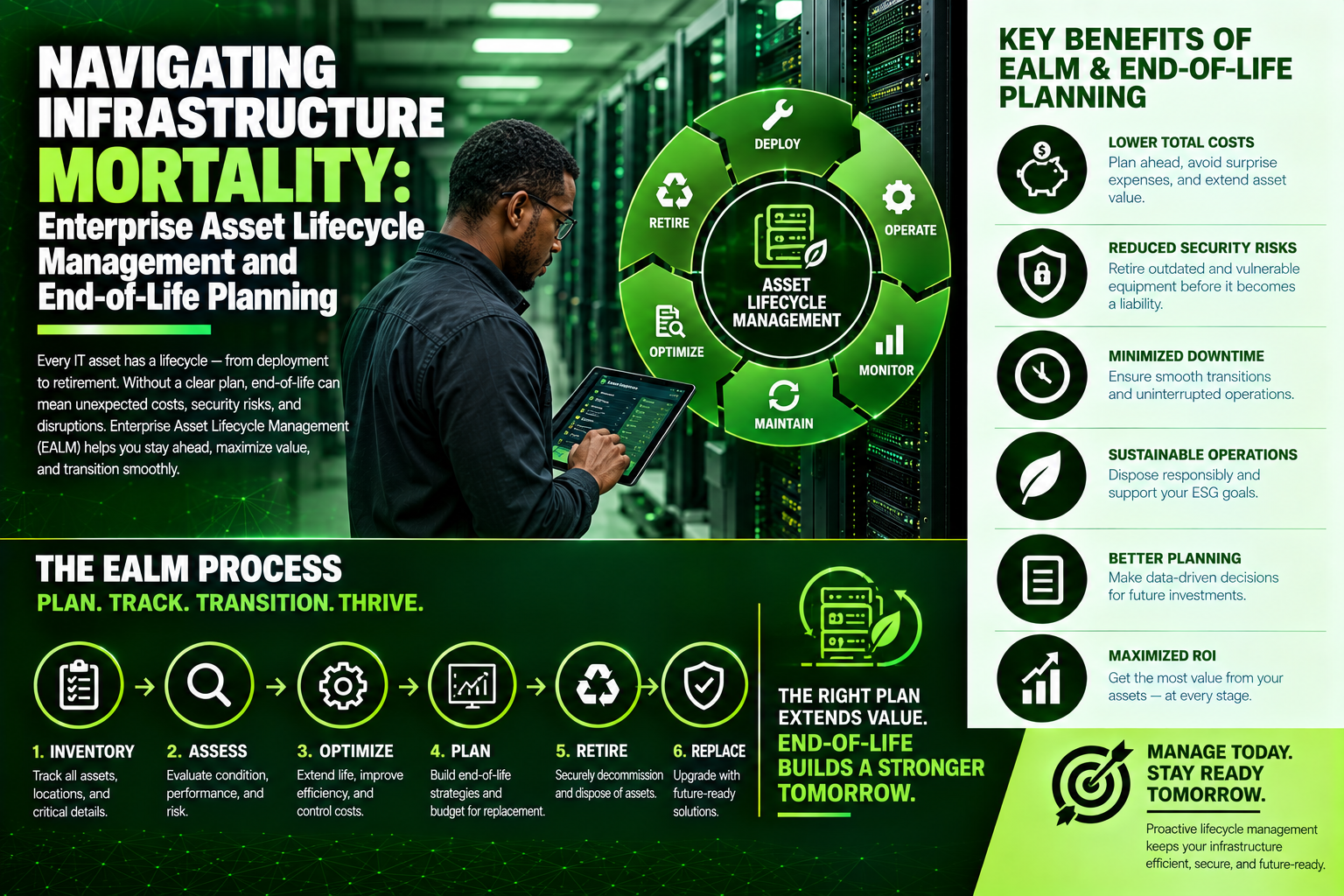
Navigating Infrastructure Mortality: Enterprise Asset Lifecycle Management and End-of-Life Planning
Ignoring the physical lifecycle of your IT hardware is an open invitation to unexpected downtime, security breaches, and ballooning support costs. Explore our comprehensive guide to Enterprise Asset Lifecycle Management, from strategic procurement and deployment to vendor EOL/EOS milestones and NIST-compliant decommissioning. Discover how Volthound Technologies delivers on-site physical audits, smart-hands execution, and clean hardware migrations to keep your infrastructure secure and fully supported.
In the fast-paced ecosystem of corporate IT, software updates and cloud migrations frequently dominate strategic discussions. However, the physical hardware underpinning those applications operates under strict physical and temporal limitations. Every core switch, security appliance, rack-mount server, and uninterrupted power supply (UPS) follows an inevitable trajectory toward physical degradation and technological obsolescence. Without a structured Enterprise Asset Lifecycle Management strategy, organizations risk relying on unmaintained hardware that exposes corporate networks to catastrophic unexpected outages, severe security vulnerabilities, and runaway maintenance costs.
The Phases of the Hardware Lifecycle
Effective Asset Lifecycle Management governs physical infrastructure from the moment of procurement planning through to secure, environmentally compliant disposal. This continuum is generally divided into five distinct operational phases.
1. Planning and Procurement
The lifecycle begins long before hardware is unboxed. Strategic procurement requires evaluating workload capacity, power density requirements, thermal profiles, and vendor support roadmaps. Organizations must look beyond initial acquisition costs and calculate Total Cost of Ownership (TCO), factoring in energy consumption, rack space requirements, annual maintenance contracts, and anticipated expansion capabilities over a three-to-five-year operational horizon.
2. Integration and Deployment
Once hardware arrives, it enters the deployment phase. This involves physical installation into server racks, structured cabling attachment, power distribution configuration, asset tagging, and initial firmware baseline configuration. Crucially, this phase requires registering the physical asset—including serial numbers, MAC addresses, switch port configurations, and exact rack elevations—into the corporate Configuration Management Database (CMDB) to establish an accurate system of record from day one.
3. Operational Maintenance and Support
During its primary production life, hardware requires continuous monitoring, environmental management, routine firmware patching, and physical maintenance. Managed maintenance contracts, such as vendor SmartNet or third-party maintenance (TPM) agreements, ensure that replacement power supplies, fan trays, or line cards are available within strict Service Level Agreements (SLAs) should physical components fail.
4. End-of-Life (EOL) and End-of-Support (EOS) Transition
As hardware ages, manufacturers announce formal lifecycle milestones. Understanding the distinction between these vendor milestones is critical for proactive risk management:
End-of-Sale (EOSa): The vendor stops manufacturing and selling the specific hardware model. The device remains fully supported, but expansion requires sourcing identical units from secondary markets.
End-of-Life (EOL) / End-of-Software-Maintenance: The vendor ceases active software development, bug fixes, and security patch generation for the platform. Running devices past this milestone introduces severe cybersecurity risks, as newly discovered vulnerabilities remain unpatched at the firmware level.
Last Day of Support (LDOS) / End-of-Support (EOS): The vendor completely terminates hardware replacement support, technical assistance, and contract renewals. Operating equipment past its LDOS turns the hardware into an unmitigated operational liability where a single component failure causes permanent, unrecoverable downtime.
5. Decommissioning and E-Waste Disposal
The final phase requires safely removing the hardware from production. Decommissioning involves systematic workload migration, graceful network unrouting, physical rack removal, and absolute data destruction. Storage drives must undergo certified cryptographic erasure or physical shredding (adhering to NIST 800-88 standards) to prevent data leakage. Finally, the physical chassis must be disposed of through accredited electronic waste recycling channels to satisfy corporate sustainability and environmental compliance standards.
The Operational Risks of Deferred Hardware Refreshes
Budget constraints and competing priorities often tempt organizations to push aging network hardware far beyond its recommended operational lifespan. While delaying capital expenditure appears cost-effective on a quarterly balance sheet, it introduces compounding operational liabilities.
First, hardware reliability degrades exponentially as components age. Electrolytic capacitors in power supplies dry out, cooling fan bearings seize, and internal solder joints experience thermal fatigue from years of continuous heating and cooling cycles. An unannounced power outage or sudden ambient temperature spike in an IDF closet often causes legacy switches to fail permanently upon rebooting, turning routine maintenance windows into multi-day emergency outages.
Second, security postures degrade rapidly when firmware updates cease. Sophisticated threat actors actively target legacy edge devices, firewalls, and remote-access switches that have passed their software maintenance cutoff dates. Because these devices no longer receive vendor security patches, they become permanent beachheads for network infiltration, lateral movement, and data exfiltration.
Third, the financial burden of maintaining legacy hardware scales inefficiently. Out-of-warranty support contracts premium-price legacy coverage, often costing significantly more annually than the pro-rated cost of deploying modern, energy-efficient replacements. Furthermore, legacy switches consume significantly more electricity per gigabit of throughput and generate greater thermal loads than modern silicon, inflating ongoing utility bills.
How Volthound Technologies Streamlines Asset Lifecycle Execution
Managing the physical lifecycle of hundreds or thousands of IT assets across geographically distributed server rooms, branch offices, and regional data centers requires specialized field execution. Volthound Technologies provides the hands-on expertise and field management necessary to bridge strategic lifecycle planning with flawless physical execution.
Volthound assists enterprise organizations at every critical hardware transition:
Physical Lifecycle Audits and CMDB Normalization: Volthound technicians perform comprehensive on-site physical audits, verifying serial numbers, rack elevation positions, and component status. Volthound reconciles physical findings against existing CMDB databases, instantly surfacing unmapped, EOL, or unsupported hardware across your entire footprint.
Turnkey Decommissioning and Secure Data Destruction: When decommissioning legacy infrastructure, Volthound handles the entire physical teardown process. Technicians un-rack equipment, trace and remove abandoned patch cabling, execute certified on-site media destruction, and provide complete chain-of-custody documentation to satisfy regulatory audit requirements.
Seamless Modernization and Deployment: Transitioning to modern hardware requires precision to avoid operational disruption. Volthound manages pre-deployment staging, physical rack-and-stack operations, structured cabling cutovers, and baseline physical testing, ensuring that new infrastructure is deployed cleanly, labeled according to strict ANSI/TIA standards, and immediately registered in your asset management systems.
Ongoing Field Support and Smart-Hands Maintenance: Volthound provides reliable on-site smart-hands execution for routine hardware maintenance, component replacements, and emergency field response, allowing internal engineering teams to remain focused on core software and architecture initiatives.
By pairing rigorous lifecycle management protocols with disciplined field execution, Volthound Technologies ensures that enterprise physical infrastructure remains secure, fully supported, and aligned with modern performance standards.
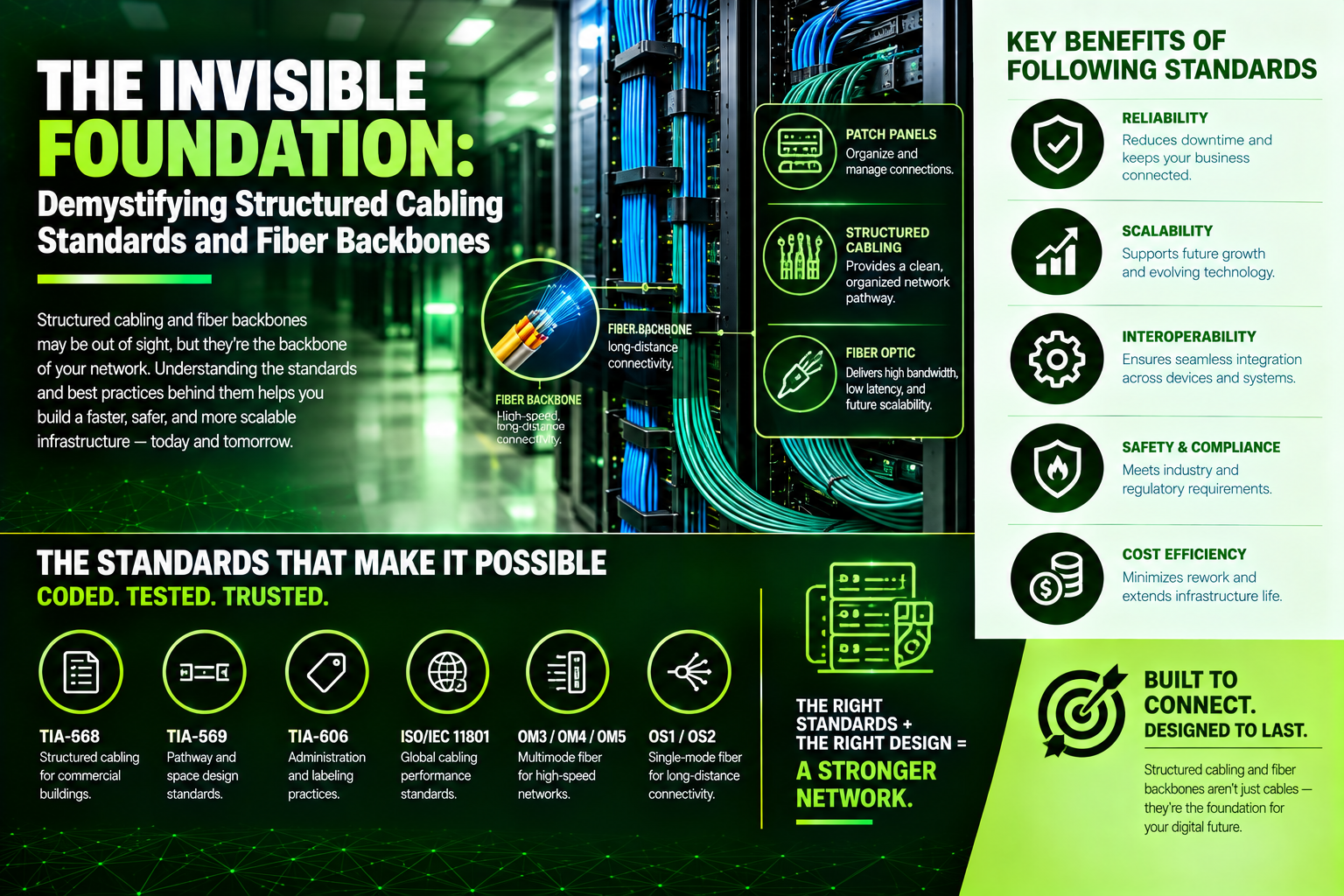
The Invisible Foundation: Demystifying Structured Cabling Standards and Fiber Backbones
Hardware is only as reliable as the physical lines that connect it. Dive into our complete guide comparing Cat6, Cat6A, and fiber optic backbones (OM4 vs. OS2). Learn how bandwidth frequencies, shielded construction, and thermal dynamics dictate enterprise network performance—and discover how Volthound Technologies provides precision cabling, fusion splicing, and Level VI certification to ensure your infrastructure is engineered for maximum uptime.
When evaluating enterprise network performance, attention naturally lands on high-profile hardware: core switches, enterprise firewalls, and Wi-Fi 6E or Wi-Fi 7 access points. Yet the highest-performing hardware on the market is fundamentally throttled if the underlying physical transport medium is improperly specified or poorly installed. Structured cabling serves as the central nervous system of any physical building footprint, determining not only current throughput capabilities but also defining the operational lifespan of the entire facility's IT investment. Understanding the distinctions between modern copper categories, shielded variants, and fiber optic backbones is essential for engineering resilient network environments.
The Evolution of Copper Cabling: Category 6 versus Category 6A
For decades, twisted-pair copper cable has been the standard workhorse for horizontal cabling runs—the physical lines connecting the Intermediate Distribution Frame (IDF) directly to end devices like desktop workstations, IP phones, and wireless access points. However, as bandwidth requirements have shifted from gigabit speeds to multi-gigabit demands, the physical construction of copper cabling has had to evolve significantly.
Standard Category 6 (Cat6) cabling was engineered to support transmission frequencies up to 250 Megahertz and reliably delivers 10-Gigabit Ethernet speeds up to a maximum distance of 55 meters under optimal conditions. Beyond 55 meters, internal crosstalk and high-frequency signal attenuation degrade performance, forcing the network to fall back to lower speed profiles. While Cat6 remains common in legacy or budget-conscious installations, modern enterprise applications—particularly high-density Power over Ethernet (PoE) devices and modern wireless access points—frequently demand the enhanced capabilities of Category 6A (Cat6A).
Category 6A ("Augmented") operates at double the frequency of standard Cat6, reaching 500 Megahertz. More importantly, Cat6A guarantees full 10-Gigabit Ethernet throughput over the entire standardized horizontal distance of 90 meters (295 feet), plus an additional 10 meters allocated for patch cords. This performance jump is achieved through stricter internal manufacturing tolerances, tighter wire pair twists, and a larger overall outer diameter. These physical enhancements dramatically mitigate Alien Crosstalk (AXT)—the unwanted electromagnetic signal interference leaked from adjacent cables bundled together in the same conduit, tray, or ceiling pathway.
Shielded versus Unshielded Construction: Navigating Interference and Heat
Within both Cat6 and Cat6A designations, network architects must choose between Unshielded Twisted Pair (UTP) and Shielded Twisted Pair (STP/FTP) designs. This decision impacts not only raw signal integrity but also physical installation complexity and total cost.
Unshielded Twisted Pair relies entirely on the precision of its internal geometric wire twists and central spline dividers to cancel out electromagnetic interference. UTP cable is lighter, significantly more flexible, easier to terminate in the field, and less expensive to deploy. For standard commercial office spaces without heavy industrial machinery or dense electrical conduits, high-grade UTP cabling is usually sufficient.
Shielded cabling introduces an internal metallic foil or braided shield wrapped around the individual wire pairs, the entire cable core, or both. This physical metallic barrier provides exceptional protection against severe external Electromagnetic Interference (EMI) and Radio Frequency Interference (RFI). Shielded runs are essential in industrial manufacturing environments, healthcare settings near high-powered imaging equipment, or overhead drop spaces running parallel to high-voltage electrical conduits.
Crucially, the rise of High-Power PoE (such as 802.3bt Class 8 delivering up to 90 Watts per port) has introduced thermal management challenges into cable bundles. High wattage passing through copper conductors generates physical heat within tightly packed ceiling pathways. Shielded cables, along with metallic conduits and ventilated ladder racks, help dissipate this thermal buildup far more effectively than unshielded bundles. Higher heat directly correlates to increased signal attenuation; therefore, managing cable bundle thermals through proper shielding and pathway design is vital for maintaining signal integrity over long distances. However, shielded cabling requires meticulous grounding and bonding at the patch panel and building ground busbar. An improperly grounded shielded system can inadvertently act as a large antenna, increasing noise and compromising network reliability rather than protecting it.
The Fiber Optic Backbone: OM4 Multi-Mode versus OS2 Single-Mode
While copper cabling dominates horizontal floor runs, the high-bandwidth backbone links that connect individual IDFs back to the central Main Distribution Frame (MDF) rely almost exclusively on fiber optic technology. Fiber optics transmit data as light pulses through pure glass strands, offering complete immunity to electromagnetic interference and supporting exponentially higher bandwidth over vast distances.
Fiber optic cabling is divided into two primary classifications: Multi-Mode Fiber (MMF) and Single-Mode Fiber (SMF).
Multi-Mode Fiber, commonly identified in modern builds by its Laser-Optimized OM3 and OM4 designations, utilizes a larger light-carrying core (typically 50 microns in diameter). This larger core allows multiple light modes or rays to propagate simultaneously from lower-cost Vertical-Cavity Surface-Emitting Laser (VCSEL) transceivers. OM4 fiber supports 10-Gigabit, 40-Gigabit, and 100-Gigabit Ethernet speeds, making it an ideal, cost-effective solution for short-distance inter-rack connections within a single server room or between adjacent closets on the same floor. However, because multiple light paths travel down the core, Modal Dispersion occurs over longer distances—causing the light pulses to overlap and degrade the signal. Consequently, OM4 multi-mode fiber reaches its practical limit for high-speed transmission at approximately 400 meters.
Single-Mode Fiber (OS2) features a minuscule glass core (typically 8 to 9 microns in diameter) that forces light down a single, precise path. By eliminating modal dispersion entirely, single-mode fiber offers nearly unlimited bandwidth potential across immense physical distances, supporting run lengths from several kilometers up to tens of kilometers without signficant signal degradation. OS2 single-mode fiber is the mandatory standard for multi-building campus backbones, high-rise vertical risers, and high-density enterprise data centers. While single-mode optical transceivers historically carried a premium price tag compared to multi-mode optics, manufacturing advances have closed this cost gap substantially. As a result, forward-looking enterprise architects increasingly deploy OS2 single-mode fiber throughout their backbone infrastructure to ensure long-term scalability without requiring future physical recabling.
Field Precision and Deployment Excellence: How Volthound Technologies Delivers
Selecting the correct cable category on paper is only half the battle; physical execution in the field determines whether those theoretical performance metrics are realized. A single over-tightened zip tie, a sharp bend exceeding the cable's minimum bend radius, or excessive untwisting of copper pairs during patch panel termination can instantly degrade a Cat6A line down to lower speeds or introduce intermittent packet drops.
This is precisely where Volthound Technologies provides essential value to enterprise clients, general contractors, and IT managers. Volthound specializes in bridge-building between high-level architectural network designs and rigorous on-site field execution.
Volthound approaches structured cabling deployments with a focus on engineering precision and long-term maintainability:
Comprehensive Pathway and Riser Engineering: Volthound field technicians conduct detailed initial site assessments to map out optimal pathway routing. They ensure cable trays, ladder racks, and J-hooks maintain correct weight distribution and adhere strictly to minimum bend-radius tolerances, preventing physical stress on sensitive copper cores and fragile glass optical strands.
Precision Fusion Splicing and Cable Dressing: For fiber backbone deployments, Volthound utilizes core-alignment fusion splicing technology rather than mechanical splices, minimizing optical loss budgets across every link. On the copper side, technicians employ meticulous wire dressing techniques—utilizing reusable hook-and-loop straps rather than abrasive plastic cable ties—to eliminate crushed jackets and maintain thermal airflow in dense wire bundles.
Level VI Field Certification and Optical Loss Testing: Volthound doesn't rely on simple continuity checks. Every installed copper link is subjected to rigorous Level VI field testing to measure Near-End Crosstalk (NEXT), Return Loss, and Alien Crosstalk, verifying full compliance with ANSI/TIA standards. Fiber runs undergo Optical Time-Domain Reflectometer (OTDR) trace analysis to verify end-to-end splice quality and confirm that light loss remains well within strict decibel budget limits.
Standardized Grounding and ANSI/TIA-606-C Labeling: To protect sensitive electronic hardware and ensure operator safety, Volthound integrates robust telecommunications grounding and bonding systems for all shielded cabling plants and metallic racks. Additionally, every cable drop, faceplate port, and patch panel position is clearly labeled following strict ANSI/TIA-606-C standards, accompanied by full as-built documentation to ensure seamless operational handoff for ongoing IT management.
By combining deep technical knowledge of cabling standards with disciplined, field-tested installation practices, Volthound Technologies ensures that your physical network layer remains a high-speed asset rather than a hidden operational bottleneck.

Verification Beyond the LED: Why Fluke and Channel Diagnostics Testing Are Essential for Mission-Critical Infrastructure
A green link light on a network switch confirms continuity, but it won't reveal crosstalk, signal attenuation, or PoE resistance unbalance that causes dropped packets. Discover why Fluke cable testing and channel diagnostics are critical for ANSI/TIA compliance—and see how Volthound Technologies delivers 100% link certification to protect your physical infrastructure.
When installing or upgrading a copper or fiber cabling system, it is tempting to plug in a cable, look for a green link light on the switch, and declare the job done. However, an illuminated link LED simply confirms basic electrical continuity—it tells you almost nothing about how that cable will handle high-bandwidth gigabit traffic, Power over Ethernet (PoE) loads, or high-density server data streams.
Underneath the surface of every network connection, subtle physical defects—such as tight bend radiuses, excessive untwisting at termination points, damaged shielding, and high-frequency crosstalk—can cause random packet loss, high latency, and intermittent network drops.
To guarantee that structured cabling meets strict ANSI/TIA and ISO/IEC industry standards, high-performing IT organizations rely on Fluke Testing alongside comprehensive Channel & Permanent Link Diagnostics.
What Is Fluke Cable Certification & Diagnostic Testing?
Fluke testing refers to field certification and diagnostic analysis performed using specialized instruments (such as the Fluke DSX CableAnalyzer™ series).
Unlike basic continuity testers that only check whether pin 1 connects to pin 1, a Fluke certifier analyzes the physical and high-frequency electrical characteristics of copper and fiber runs. It subjects the physical layer to a rigorous battery of signal frequency sweeps, generating an unalterable pass/fail certification report for every individual drop.
Key Parameters Evaluated During Diagnostic Certification
When a certification analyzer tests a Cat6, Cat6A, or fiber optic link, it measures several critical physical and electrical parameters:
Wiremap: Verifies proper pin-out configurations and identifies physical faults like open circuits, short circuits, reversed pairs, and split pairs.
Near-End Crosstalk (NEXT) & PS-NEXT: Measures signal leakage between wire pairs inside the cable jacket. Excessive untwisting during jack termination degrades NEXT, causing data corruption and packet re-transmissions.
Insertion Loss (Attenuation): Measures signal strength loss along the total length of the cable run, flagging runs that exceed maximum length limits (100 meters for standard copper channels).
Return Loss: Detects signal reflections caused by impedance variations, kinks in the wire, or poor-quality connectors.
DC Resistance Unbalance: Essential for modern Power over Ethernet (PoE+ / PoE++). Unbalanced resistance between conductors causes heat build-up and degrades data transmission to IP cameras, access points, and smart lighting.
Optical Loss & OTDR (for Fiber): Measures total light loss in decibels (dB) across fiber optic strands and pinpoints the exact location of micro-bends, dirty connectors, or faulty splices.
Permanent Link vs. Channel Testing Explained
Understanding the scope of your test is crucial when validating structured cabling:
1. Permanent Link Testing
Permanent Link testing evaluates the fixed portion of the cabling infrastructure—stretching from the patch panel in the telecommunications room (MDF/IDF) to the wall outlet/keystone jack at the work area. Because it excludes temporary equipment patch cords, this is the strict, standardized test required by cable manufacturers to issue 15- to 25-year structural warranties.
2. Channel Testing
Channel testing evaluates the entire end-to-end communication path, including the permanent link plus the equipment patch cords on both ends. This validates real-world performance as equipment is actively connected, ensuring that worn or inferior patch cables don't bottleneck network traffic.
The Operational Risks of Skipping Field Certification
Hidden Packet Loss & Latency: Uncertified cables may pass basic continuity checks but fail under full network load, forcing switches to re-transmit dropped packets and slowing down cloud application response times.
PoE Overheating & Fire Hazards: High-wattage PoE++ devices draw up to 90W over copper pairs. Unbalanced resistance or substandard terminations cause cable bundles inside ceilings to overheat, posing physical fire hazards.
Voided Hardware Warranties: Major cabling manufacturers will not issue system warranties without certified, unedited Fluke test results submitted for every single drop.
How Volthound Technologies Guarantees Cable Quality for Clients
Ensuring your physical cabling infrastructure can support high-speed network demands requires calibrated diagnostic gear and certified technicians. Volthound Technologies provides complete structured cabling, Fluke testing, and channel certification services to give enterprise clients total confidence in their physical layer.
Here is how Volthound Technologies delivers verified cabling excellence:
100% Link Certification with Calibrated Fluke Equipment: Volthound field engineers test every newly installed or legacy cable run using industry-leading Fluke Versiv™ cable analyzers, verifying full compliance with ANSI/TIA-568 standards.
Comprehensive Pass/Fail Audit Documentation: Volthound provides clients with full, exportable PDF test reports for every port, detailing exact cable lengths, frequency margins, and performance metrics for strict audit compliance.
Advanced Cable Troubleshooting & Remediation: When existing runs fail or show high bit-error rates, Volthound uses Time-Domain Reflectometry (TDR) to pinpoint the exact distance to a fault (such as a crushed cable behind drywall or a bad punchdown) for rapid repair.
Manufacturer Warranty Qualification: By delivering certified Fluke Permanent Link test results, Volthound qualifies your installation for long-term structured cabling system warranties backed by leading component manufacturers.
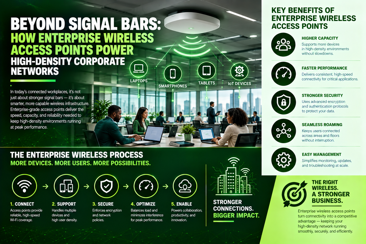
Beyond Signal Bars: How Enterprise Wireless Access Points Power High-Density Corporate Networks
Frozen video calls and Wi-Fi dead zones in crowded conference rooms aren't an ISP issue—they're a wireless architecture problem. Discover how enterprise Wireless Access Points (WAPs) leverage Wi-Fi 6E/7, PoE cabling, and active roaming controllers to handle high client density, and see how Volthound Technologies conducts RF site surveys to deliver seamless, zero-drop coverage across your facility.
In today’s modern workplace, seamless connectivity is no longer a luxury—it is as essential as electricity. Employees move fluidly between conference rooms, desks, and open collaboration spaces with laptops, smartphones, tablets, and IoT devices.
Yet, many organizations struggle with frozen video calls, unexpected Wi-Fi dropouts, and frustrating "dead zones" in high-density areas like boardrooms or event halls.
When network coverage fails, the blame often falls on the internet service provider. However, the true culprit is almost always an improperly deployed wireless network architecture—specifically, misused or poorly placed Wireless Access Points (WAPs).
What Is an Enterprise Wireless Access Point?
A Wireless Access Point (WAP) is a dedicated networking device that connects to a wired Ethernet switch or router, transmitting radio frequency (RF) signals to establish a local wireless network (WLAN).
Unlike consumer-grade Wi-Fi routers—which combine a router, switch, and access point into a single box—enterprise WAPs operate as distributed network nodes. Multiple access points are deployed across a facility to create a unified, seamless wireless mesh that allows hundreds of devices to connect concurrently without experiencing performance degradation.
Common Pitfalls of Enterprise Wi-Fi Deployments
1. Coverage vs. Capacity Confusion
Installing a few high-powered access points might cover a building's physical footprint, but it overlooks client density. In a crowded conference room, dozens of active devices competing for airtime on a single WAP cause channel congestion, latency spikes, and packet loss.
2. Signal Attenuation & Physical Obstacles
Radio signals degrade when passing through physical barriers. Concrete walls, metallic structural beams, low-E glass windows, and even metal ductwork absorb or reflect Wi-Fi signals, creating severe coverage gaps if not accounted for during design.
3. Co-Channel Interference (CCI)
Placing access points too close together or failing to configure non-overlapping radio channels causes adjacent WAPs to interfere with one another, effectively reducing total network capacity and slowing down all connected clients.
4. Sticky Client Syndrome
Without centralized wireless controller management, mobile devices remain connected to a distant access point with a weak signal instead of automatically roaming to a closer, stronger access point as employees walk through the building.
Key Pillars of a Modern Enterprise Wireless Architecture
Wi-Fi 6 / 6E / Wi-Fi 7 Standards: Modern WAPs leverage OFDMA (Orthogonal Frequency-Division Multiple Access) and MU-MIMO (Multi-User, Multiple-Input, Multiple-Output) technology to transmit data to multiple devices simultaneously, eliminating queue times in dense environments.
Power over Ethernet (PoE/PoE+): Enterprise WAPs draw both data and electrical power through a single Cat6/Cat6A cable, allowing flexible ceiling or wall mounting without requiring adjacent electrical outlets.
Centralized Cloud Controller Management: Cloud-managed systems dynamically adjust radio power levels, assign non-interfering channels, and manage client roaming handoffs seamlessly across all site access points.
Granular Network Segmentation (VLANs): Modern wireless architectures broadcast multiple SSIDs from a single physical WAP, isolating internal corporate traffic from guest access, smart building sensors, and IoT devices for maximum security.
How Volthound Technologies Optimizes Wireless Infrastructure for Clients
Designing, cabling, and deploying a reliable enterprise Wi-Fi network requires deep RF engineering experience, physical installation precision, and meticulous network tuning. Volthound Technologies provides complete, end-to-end wireless access point solutions that guarantee seamless, high-density coverage for any commercial facility.
Here is how Volthound Technologies delivers exceptional wireless environments:
Predictive & Active RF Site Surveys: Volthound engineers use industry-leading diagnostic software to model signal propagation, wall attenuation, and client density prior to installation—ensuring exact AP count and location placement.
Certified Low-Voltage Cabling & Mounting: Volthound pulls certified Cat6/Cat6A drops to every AP location, neatly terminates connections, and securely mounts access points to drop-ceiling grids, high-bay warehouse trusses, or exterior walls.
Enterprise Controller & Security Configuration: Volthound configures cloud-based wireless controllers with seamless 802.11r roaming protocols, custom guest portals, and isolated VLAN security segments tailored to your IT policies.
Post-Deployment Validation & Spectrum Audits: After installation, Volthound conducts physical walk-through audits using spectral analysis tools to measure actual signal strength (RSSI), signal-to-noise ratio (SNR), and throughput speeds, delivering verified performance reports.
Beyond the Modem: Why Your ISP Gateway Is Throttling Your Enterprise Network
Paying for gigabit fiber but still experiencing lagging video calls and network dropouts? The culprit is often your stock ISP gateway. Discover why all-in-one provider routers throttle enterprise workloads—and see how Volthound Technologies configures bridge mode, multi-WAN failover, and dedicated security firewalls to unlock true zero-downtime connectivity.
When businesses sign up for high-speed gigabit fiber or business-grade broadband, they expect blazing-fast speeds and uninterrupted connectivity. Yet, many corporate offices, retail stores, and remote facilities experience frequent dropouts, lagging VoIP calls, and sluggish cloud performance.
When IT teams investigate, the root cause is rarely the internet line itself. Instead, the bottleneck resides right at the front door: the ISP Gateway.
Understanding the limitations of ISP-provided gateways—and knowing how to integrate them into an enterprise network architecture—is the difference between an unreliable network and a high-availability infrastructure.
What Is an ISP Gateway?
An ISP Gateway is an all-in-one networking device supplied by your Internet Service Provider that combines three distinct hardware roles into a single box:
The Modem / Optical Network Terminal (ONT): Translates incoming signals (coaxial, copper, or fiber optic) from the provider into standard Ethernet data.
The Router: Directs data traffic between your local internal network (LAN) and the public internet (WAN).
The Wi-Fi Access Point & Switch: Broadcasts wireless signals and provides a handful of local LAN ports for direct physical connections.
While an all-in-one gateway works well for residential settings, relying on a stock ISP gateway to handle enterprise-grade network traffic creates severe performance bottlenecks.
Key Limitations of Stock ISP Gateways in Business Settings
Hardware Resource Throttling: Consumer and entry-level ISP gateways feature low-powered processors and limited RAM. When subjected to dozens of concurrent laptops, smartphones, IP cameras, and VoIP desk phones, their NAT (Network Address Translation) tables overflow, causing spontaneous reboots and latency spikes.
Lack of Advanced Security Control: Default gateways offer minimal firewall controls, lacking modern Intrusion Prevention Systems (IPS), deep packet inspection, or granular VLAN isolation required to protect sensitive financial and corporate data.
Bridge Mode & IP Passthrough Failures: Integrating an ISP gateway with an enterprise firewall requires setting the gateway to "Bridge Mode" to pass the public static IP through without Double NAT. Many stock gateways handle bridge mode poorly, causing intermittent connection drops.
Zero WAN Redundancy: Stock gateways rely on a single physical line. If an underground fiber cable gets cut during street construction, your entire business goes dark without an automatic secondary connection (cellular failover or secondary ISP).
The Anatomy of an Enterprise Gateway Setup
To achieve true business continuity, enterprise networks bypass the routing and Wi-Fi functions of the stock ISP gateway entirely:
Step 1: Bridge Mode Activation
The ISP gateway is configured purely as a passthrough modem (ONT), handing off the raw public IP address directly to an enterprise-grade security firewall.
Step 2: Dedicated Enterprise Firewall / Router Deployment
A high-throughput firewall (such as Fortinet, Cisco Meraki, or Palo Alto) assumes all routing, VPN, DHCP, and security filtering duties, utilizing dedicated network processors designed to handle heavy multi-gigabit traffic.
Step 3: Multi-WAN Failover & Load Balancing
Secondary connections (such as 5G/LTE wireless or a secondary broadband provider) connect directly to the main firewall. If the primary ISP drops line sync, traffic automatically shifts to the secondary WAN in milliseconds without dropping active VoIP calls or cloud sessions.
How Volthound Technologies Optimizes ISP Gateways and Perimeter Networks
Configuring ISP handoffs, static IP routings, and high-availability firewalls requires specialized networking expertise. Volthound Technologies provides end-to-end edge network engineering to ensure your ISP gateway integration delivers zero-downtime performance.
Here is how Volthound Technologies optimizes client gateway infrastructure:
ISP Handoff & Bridge Mode Configuration: Volthound network engineers interface directly with your service provider to reconfigure ISP gateways into pure bridge or IP passthrough mode, eliminating Double NAT issues and unlocking maximum throughput.
Enterprise Firewall & Edge Router Installation: Volthound deploys and configures enterprise security gateways with custom VLAN segmentation, Quality of Service (QoS) priorities for VoIP traffic, and encrypted site-to-site VPN tunnels.
Multi-WAN & LTE/5G Redundancy Design: Volthound integrates multi-carrier WAN failover systems, ensuring that if your primary ISP gateway loses connection, your business seamlessly switches to a backup circuit without operational disruption.
Rack Integration & Structured Cabling: Volthound mounts and organizes gateway equipment inside dedicated server racks with clean, labeled Cat6A/fiber patch cables, dedicated UPS battery backups, and thermal management.
Uptime Is Everything: Master Data Center Maintenance Before Failure Strikes
Reactive IT maintenance isn't a strategy—it's an outage waiting to happen. Discover the critical pillars of data center maintenance, from thermal management to UPS load-bank testing, and see how Volthound Technologies uses infrared thermography, rack remediation, and preventive servicing to keep your mission-critical infrastructure running 24/7/365.
Modern businesses run on digital infrastructure. Whether processing financial transactions, hosting cloud applications, or supporting real-time communication, a company’s data center is its beating heart.
When a facility experiences unscheduled downtime, the costs mount instantly: lost revenue, damaged brand reputation, and compromised critical data. Yet, many organizations still rely on reactive maintenance—fixing components only after they break.
To guarantee high availability and operational efficiency, leading enterprises rely on proactive, structured Data Center Maintenance.
The Three Pillars of Data Center Maintenance
Maintaining an enterprise-grade facility requires a holistic approach covering physical, electrical, and mechanical systems.
1. Environmental and Thermal Management
High-density server racks generate immense heat. Effective thermal maintenance involves inspecting Computer Room Air Conditioning (CRAC) and Computer Room Air Handler (CRAH) units, cleaning air filters, checking coolant levels, and monitoring hot/cold aisle containment to eliminate hotspots that degrade hardware.
2. Power Quality and Redundancy Testing
Power interruptions are among the most common causes of data center outages. Regular electrical maintenance requires testing Uninterruptible Power Supply (UPS) battery banks, inspecting automatic transfer switches (ATS), and performing load-bank tests on backup diesel generators under full simulated loads.
3. Structured Cabling and Cable Management
Over time, adding or removing connections without strict oversight leads to restricted airflow and unmanageable cable tangles. Routine cabling maintenance involves cleaning fiber connections, replacing worn patch cords, and organizing runs to maintain proper ventilation inside racks.
Predictive vs. Preventive Maintenance: A Quick Comparison
Preventive Maintenance (PM): Scheduled, calendar-based inspections and servicing (e.g., quarterly battery checks or semi-annual generator testing). It catches routine wear-and-tear before failure occurs.
Predictive Maintenance (PdM): Sensor-driven, real-time monitoring that uses thermal imaging, vibration analysis, and telemetry to predict exact component degradation timelines before a fault ever happens.
How Volthound Technologies Elevates Data Center Maintenance
Keeping complex server facilities running at peak performance demands field experience, specialized diagnostic tools, and strict adherence to industry standards. Volthound Technologies provides complete, end-to-end data center maintenance services engineered to maximize uptime and extend hardware lifecycles.
Here is how Volthound Technologies protects client infrastructure:
Comprehensive Site Audits & Thermal Imaging: Volthound technicians use advanced infrared thermography to identify hidden electrical overloads and cooling inefficiencies before they trigger equipment failure.
Routine Preventive Maintenance Schedules: Volthound designs customized, non-disruptive maintenance routines for power systems, backup generators, cooling units, and cable infrastructure to keep operations compliant and reliable.
Rack Remediation & Cable Cleanup: Volthound turns messy server closets and chaotic racks into color-coded, labeled, and airflow-optimized environments, restoring thermal health and simplifying future servicing.
24/7 Rapid Incident Response & SLA Support: When unexpected hardware anomalies arise, Volthound delivers rapid on-site technical support to diagnose, isolate, and resolve issues with minimal business impact.
Zero-Downtime Migration: How to Move Critical Infrastructure Without Sacrificing Business Continuity
Moving enterprise server racks and core switches isn't just a moving job—it's high-stakes system engineering. Discover the five essential phases of zero-downtime equipment migration, from ESD-safe logistics to port-for-port mapping, and see how Volthound Technologies executes flawless IT relocations that protect your data and business continuity.
Relocating an enterprise data center, server closet, or network rack assembly is one of the highest-stakes technical undertakings an IT organization can face.
When multi-million-dollar server racks, high-density storage arrays, core switches, and fiber patch panels must be powered down, physically extracted, transported, and re-architected in a new facility, the risk profile escalates rapidly. Extended business downtime, hardware shock damage, lost data, and misconfigured network routing keep technology leaders and executives awake at night.
Physical equipment migration is far more than a specialized moving job—it is a complex system engineering process. Executing a successful physical move requires meticulous pre-migration auditing, precise sequence-controlled shutdowns, shock-protected transit, and flawless re-commissioning at the destination.
The 5 Essential Phases of an Enterprise Equipment Migration
A successful infrastructure migration relies on a strict, disciplined sequence that leaves zero room for guesswork or on-the-fly decisions:
1. Pre-Move Technical Audits and Infrastructure Mapping
Long before a single cable is disconnected, engineers conduct an exhaustive physical and digital audit of the source environment. Every server chassis, power distribution unit (PDU), patch panel port, and network switch is cataloged into a digital schema. Power draw, thermal requirements, rack elevation units (U-space), and inter-system network dependencies are fully documented to ensure complete compatibility with the destination rack layout and power circuits.
2. Dependency-Aware, Sequence-Controlled Shutdowns
Components cannot simply be powered off simultaneously. System architectures require strict, dependent shutdown sequences to prevent data corruption or file system crashes. For instance, application services and virtual machines must be gracefully suspended first, followed by database engines, storage area networks (SANs), and finally core network routers and firewalls.
3. ESD-Safe De-Racking and Specialized Anti-Static Logistics
Sensitive electronic components are highly vulnerable to electrostatic discharge (ESD), mechanical shock, and vibration during transit. Hardware is carefully un-racked by trained technicians, wrapped in specialized anti-static protective materials, and secured inside custom-padded, climate-controlled transport enclosures designed to absorb road vibration.
4. Precision Destination Re-Installation and Cable Dressing
Upon arrival at the new site, equipment is re-racked according to pre-engineered elevation blueprints. Patch cords, fiber optic jumpers, and power feeds are routed, labeled, and cleanly dressed using horizontal and vertical cable managers. Adhering to strict cabling standards at this stage ensures optimal rack airflow and prevents cable spaghetti from forming.
5. System Re-Commissioning, Physical Validation, and Hand-Off
Once re-racked and powered, engineers systematically initiate the boot sequence in reverse order. The team conducts physical layer verification, tests link speeds, verifies VLAN routings, and checks hardware health metrics alongside internal IT teams before officially declaring the migration complete and handing over operations.
Primary Risks of Unplanned Migration Practices
Unscheduled Extended Downtime: Improper shutdown sequences or missing cable mapping schemas can easily turn a planned four-hour weekend maintenance window into a multi-day business outage while technicians struggle to trace connections.
Physical Hardware Degradation: Traditional hard drives, optical interfaces, and circuit boards are highly sensitive to physical impact. Moving hardware without custom shock-absorbing packaging can cause mechanical drive head crashes or unseated internal components.
Destination Cable Chaos: Relocating hardware without a port-for-port mapping document frequently results in tangled cable bundles, blocked cooling vents, misconfigured switch ports, and hours of troubleshooting missing VLAN connections.
How Volthound Technologies Guarantees Flawless Equipment Migration
Migrating mission-critical infrastructure demands specialized technical expertise, dedicated physical tooling, and disciplined project management. Volthound Technologies provides end-to-end IT relocation and equipment migration services engineered to minimize operational risk and eliminate unscheduled downtime.
Here is how Volthound Technologies delivers seamless hardware relocations:
Comprehensive Pre-Migration Mapping & Schema Design: Volthound engineers conduct detailed site audits at both origin and destination facilities. Every cable, port, rack unit, and power circuit is cataloged in a precise digital schema prior to move day.
Certified De-Racking & ESD-Safe Logistics: Volthound technicians execute physical de-installation using specialized anti-static handling gear, custom shock-absorbing crates, and secure, climate-controlled transport vehicles.
Clean Re-Racking & Structured Cable Management: At the target facility, Volthound mounts hardware according to engineered blueprints, dresses cables cleanly with horizontal and vertical managers, and applies standardized port labels for effortless future maintenance.
Post-Migration Testing & Validation: Volthound executes physical layer verification, power redundancy testing, and port connectivity checks alongside your internal IT team to guarantee 100% system functionality before going live.
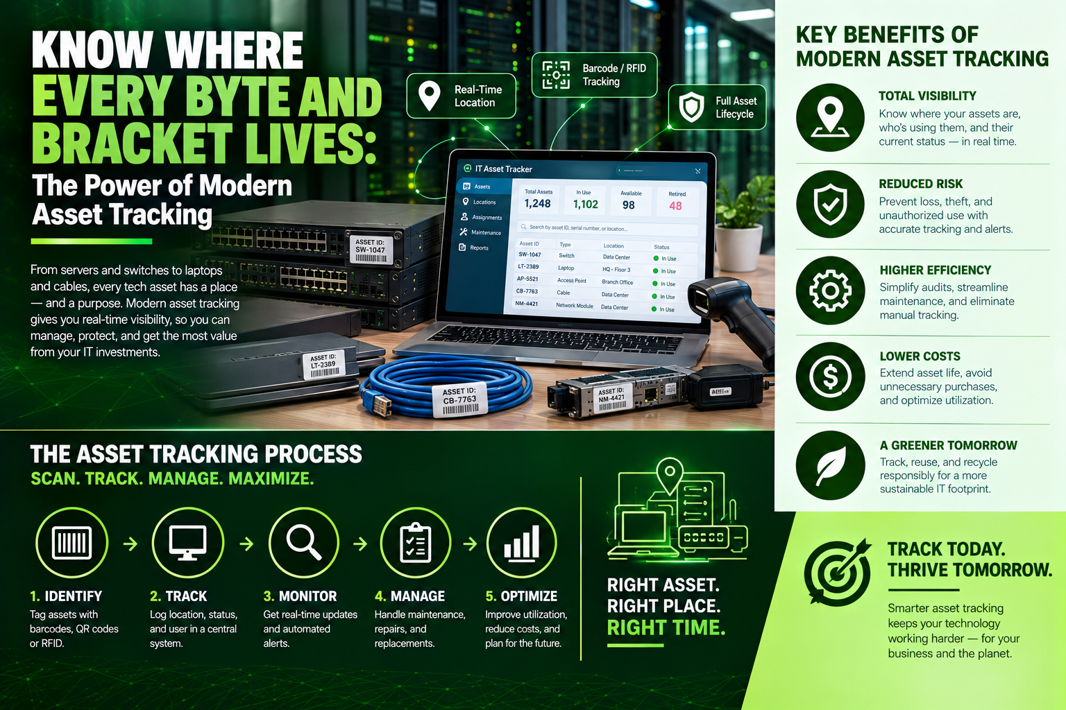
Know Where Every Byte and Bracket Lives: The Power of Modern Asset Tracking
Unrecorded server blades sitting in dark racks and missing laptops aren't just headaches—they're major security risks and financial leaks. Discover how modern enterprise asset tracking bridges the physical-to-digital gap using RFID, spatial mapping, and CMDB sync, and see how Volthound Technologies gives you total visibility over every byte and bracket in your infrastructure.
As enterprises grow across hybrid offices, multi-floor data centers, and remote operational sites, tracking physical hardware quickly transforms from a simple administrative chore into a massive operational headache. Laptops vanish during employee transitions, high-value server blades sit unrecorded in dark racks, and maintenance contracts continue to drain budgets for hardware that was retired years ago.
This dangerous operational blind spot is where Asset Tracking—a foundational capability within Site Surveys, Audits & Asset Management—becomes vital to achieving financial clarity, regulatory compliance, and bulletproof infrastructure security.
What Is Asset Tracking?
Asset tracking is the continuous, systematic process of capturing physical, spatial, operational, and financial data for every piece of hardware across your infrastructure throughout its operational lifecycle.
Rather than relying on static, outdated spreadsheets that are manually updated once a year, modern asset tracking establishes real-time visibility over exact physical locations, unique serial numbers, departmental ownership, maintenance histories, and warranty lifecycles.
It serves as the critical, real-time bridge connecting your physical workspace directly to your digital Configuration Management Database (CMDB) or IT Asset Management (ITAM) platform.
Key Benefits of Enterprise Asset Tracking
Eliminating "Ghost Assets": A primary benefit of asset tracking is identifying phantom hardware. Businesses regularly pay active maintenance contracts, software licensing fees, and local property taxes on equipment that has been decommissioned, stolen, or lost. Tracking closes this gap permanently.
Rapid Security Incident Response: During a security breach or physical theft, time is critical. Modern tracking allows your security team to instantly map a compromised device's serial number back to its precise physical location, assigned user, sub-network segment, and active switch port.
Streamlined Financial and Compliance Audits: Passing financial, SOC 2, or industry-specific regulatory audits requires verifiable proof of physical asset custody. Detailed tracking provides timestamped chain-of-custody logs and historical location audits, eliminating audit prep panic.
Proactive Hardware Lifecycle Management: By tracking the age, deployment date, and thermal environment of your hardware, IT leaders can plan hardware refresh cycles based on actual usage metrics and warranty timelines—preventing unexpected failure during mission-critical tasks.
The Core Pillars of a Modern Asset Tracking Architecture
A mature asset tracking framework relies on three interconnected layers to maintain absolute physical-to-digital parity:
1. High-Durability Barcode & RFID Identification
Physical devices require permanent, tamper-evident identifiers. Enterprise deployments use specialized thermal-transfer metallic barcode labels, QR tags, or active/passive Radio Frequency Identification (RFID) tags. These tags are designed to withstand high thermal environments inside server racks, physical abrasion, and chemical cleaning agents without degrading.
2. Automated Network & Agent Discovery
Physical tagging is paired with automated network scanning software. Discovery agents continuously audit IP ranges, MAC address tables, and active switch ports, automatically cross-referencing connected devices against physical serial numbers in your asset database to catch un-tagged or rogue devices immediately.
3. Spatial, Room, and Rack-Level Mapping
Asset tracking goes beyond knowing what building a device resides in. Advanced tracking logs spatial positioning down to the exact floor, telecommunications room, server rack chassis, and vertical rack unit (U-space) location—ensuring field technicians can walk directly to any device without searching.
How Volthound Technologies Transforms Asset Tracking for Clients
Managing thousands of hardware assets distributed across complex corporate environments demands specialized field expertise, advanced diagnostic tooling, and meticulous data handling. Under their specialized Site Surveys, Audits & Asset Management practice, Volthound Technologies delivers end-to-end asset tracking solutions that give organizations complete, 100% infrastructure visibility.
Here is how Volthound Technologies optimizes your asset lifecycle:
Comprehensive On-Site Physical Audits & Tagging: Volthound sends certified field engineers directly to your facilities to audit every piece of hardware. They systematically apply high-durability RFID, barcode, and QR tags to servers, switches, patch panels, workstations, and peripherals.
CMDB & ITAM System Integration: Volthound synchronizes physical audit findings directly into your existing ITAM or enterprise management database, eliminating manual entry errors and creating a single, authoritative source of truth.
Precision Rack-Level Spatial Mapping: Volthound maps server room layouts down to the exact shelf and vertical unit space, equipping your internal IT staff with visual digital schematics to pinpoint any physical asset instantly.
Lifecycle Governance & Secure Decommissioning: When assets reach end-of-life, Volthound manages physical un-racking, chain-of-custody logging, certified data destruction, and asset retirement updates—guaranteeing zero residual ghost assets remain on your books.
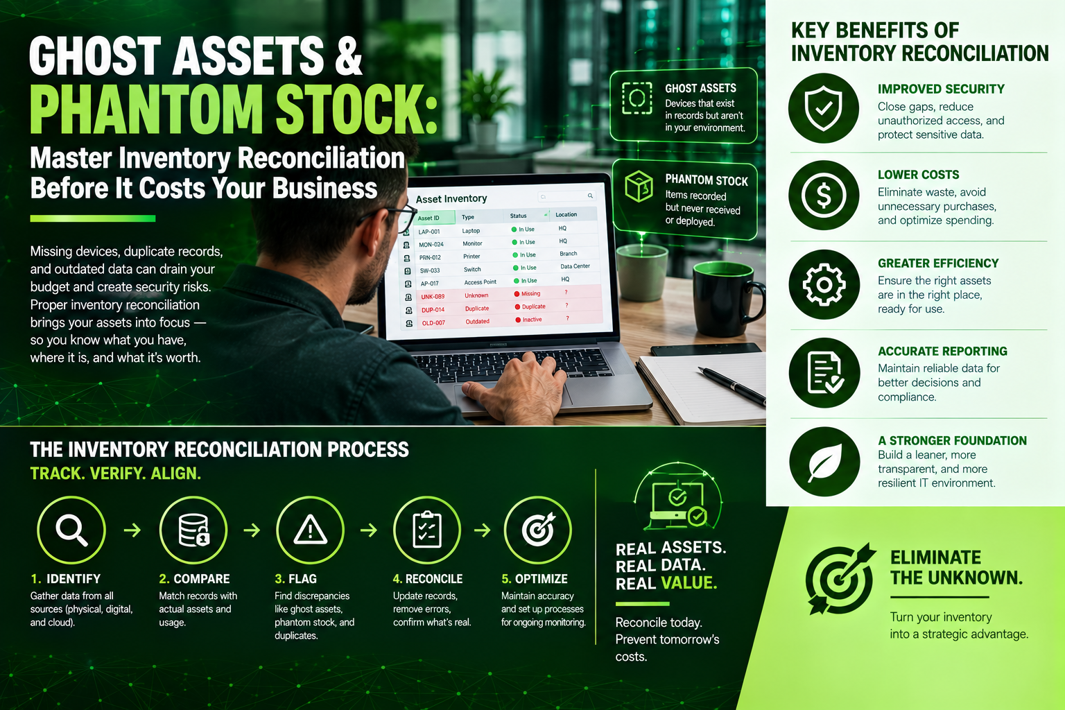
Ghost Assets and Phantom Stock: Master Inventory Reconciliation Before It Costs Your Business
Paying insurance and taxes on "ghost assets" that were decommissioned years ago? Discover why inventory reconciliation is critical for modern enterprises—from stopping stockouts to passing audits—and see how Volthound Technologies combines RFID tagging, automated CMDB discovery, and physical audits to keep your asset records 100% accurate.
Imagine reviewing your financial ledger or warehouse dashboard and seeing 500 high-value network switches listed as "in stock." You land a major enterprise deployment, dispatch your field technicians to pull the inventory, and discover... the shelves are completely empty.
Or consider an internal audit revealing that your business has been paying thousands of dollars annually in software licensing, maintenance contracts, and insurance for 50 "ghost devices" that were physically decommissioned three years ago.
These operational breakdowns stem from a single root cause: a breakdown in Inventory Reconciliation.
What Is Inventory Reconciliation?
Inventory reconciliation is the systematic process of matching physical inventory or physical IT asset counts against recorded digital ledger data (such as ERP, WMS, or ITAM systems).
When discrepancies occur—known as inventory variance—reconciliation isolates the root cause (whether that is theft, unrecorded damage, mislabeling, data-entry errors, or improper decommissioning) and systematically aligns the digital records with physical reality.
The core reconciliation workflow follows a strict sequence:
Physical Asset Counting: Field technicians or warehouse auditors scan and record physical items using RFID tags, QR codes, or serial numbers.
Digital Ledger Comparison: Specialized software compares the physical scan data directly against historical ERP, WMS, or ITAM records.
Variance Identification & Investigation: Discrepancies between expected counts and actual counts are flagged automatically for investigation.
Root Cause Resolution: Technicians trace the variance to specific events, such as unrecorded hardware transfers, administrative typos, or transit damage.
Ledger Adjustment & System Alignment: Official inventory databases are updated to reflect exact physical counts, closing the gap between accounting and physical assets.
Why Inventory Reconciliation Is Critical for Modern Enterprises
Eliminating "Ghost Assets": Inactive hardware or missing stock left on balance sheets creates inaccurate financial reporting, inflates insurance premiums, and generates unnecessary tax liabilities.
Preventing Stockouts and Project Delays: Unreliable inventory counts lead to delayed customer rollouts, missed SLAs, and emergency re-ordering at premium expedited shipping rates.
Mitigating Theft and Shrinkage: Regular reconciliation cycles detect unauthorized removals or unrecorded transfers early, stopping minor discrepancies from turning into major financial losses.
Enforcing Regulatory and Audit Compliance: Financial standards (such as GAAP and IFRS) and cybersecurity frameworks mandate accurate, verifiable records of physical and digital assets.
The 4 Main Types of Inventory Reconciliation
1. Wall-to-Wall Physical Audits
This traditional method involves temporarily pausing operational activity to manually count every single item across an entire facility. While highly thorough, wall-to-wall counts are extremely labor-intensive, costly due to operational downtime, and prone to human error if conducted infrequently.
2. Cycle Counting
Cycle counting is a continuous auditing method where smaller subsets of inventory are audited on a rotating schedule (such as daily or weekly). High-value, critical, or fast-moving assets are audited more frequently, ensuring continuous accuracy without shutting down daily operations.
3. Automated RFID and Barcode Reconciliation
By leveraging handheld scanners, mobile apps, or fixed RFID gates, technicians scan physical assets automatically. This approach cross-references physical serial numbers against digital databases in real time, drastically reducing human audit errors and completing counts in a fraction of the time.
4. Automated IT Endpoint Scanning
For digital infrastructure, automated discovery tools scan network segments to detect active IP addresses, connected hardware endpoints, and installed software licenses. This continuously reconciles physical IT assets with your Centralized Management Database (CMDB).
How Volthound Technologies Streamlines Inventory Reconciliation
Reconciling enterprise inventory—whether physical warehouse stock, server rack hardware, or multi-location IT infrastructure—requires deep technical precision, automated tools, and structured workflows. Volthound Technologies provides end-to-end asset management and inventory reconciliation solutions designed to eliminate manual data entry errors and keep your records 100% accurate.
Here is how Volthound Technologies transforms inventory operations:
Barcode and RFID Tagging Deployments: Volthound designs and applies standardized, high-durability barcode, QR, and RFID asset tagging solutions, turning manual physical counts into rapid, digital scans.
Automated Asset Discovery & CMDB Synchronization: For technology infrastructure, Volthound implements network-level automated discovery tools that constantly reconcile active hardware, connected endpoints, and software licenses against your centralized database.
Physical-to-Digital Audit Services: Volthound's certified technicians conduct comprehensive physical audits of server rooms, warehouses, and remote offices, identifying unrecorded equipment, missing serial numbers, and legacy hardware.
Chain-of-Custody & Decommissioning Tracking: When hardware reaches end-of-life, Volthound manages physical removal, data sanitization, and asset tag retirement, ensuring your digital inventory ledger updates instantly with zero residual "ghost assets."

Clean Slate Tech: How Proper E-Waste Preparation Protects Your Business, Data, and Planet
Upgrading your corporate hardware is great for business, but leaving old servers and laptops in a storage closet creates serious data security and compliance risks. Discover the four essential steps of enterprise e-waste preparation—and see how Volthound Technologies handles certified data destruction, asset tracking, and zero-landfill IT asset disposition.
Upgrading your company’s hardware is an exciting milestone. Faster servers, crisp monitors, and high-performance laptops boost productivity and boost morale. But behind every IT refresh lies an uncomfortable question: What happens to the mountains of decommissioned tech left in the storage room?
Discarded electronics—known as e-waste—are the fastest-growing waste stream on earth. Beyond the environmental hazard of toxic heavy metals leaking into ecosystems, old hardware carries significant operational risks: corporate data leaks, regulatory fines, and missed opportunities for asset recovery.
Throwing old hardware into a dumpster isn't just irresponsible—it's a massive compliance liability. Managing e-waste correctly starts long before a recycling truck arrives. It begins with E-Waste Preparation.
The 4 Crucial Steps of E-Waste Preparation
Before handing off end-of-life IT assets for recycling or refurbishment, enterprise IT teams must execute a structured preparation workflow. Skipping a single step can expose sensitive corporate data or result in hazardous material violations.
1. Complete Data Sanitization & Destruction
Deleting files or formatting a hard drive does not erase data; specialized tools can recover "deleted" information in minutes.
Software Wiping: Perform NIST 800-88 compliant multi-pass overwrites on reusable hard drives and SSDs.
Physical Destruction: Shred or degauss drives containing sensitive financial, medical, or proprietary IP that cannot be repurposed.
2. Hazard Isolation & Battery Removal
Discarded electronics often contain volatile components that pose immediate safety hazards during transport.
Lithium-Ion Batteries: Remove laptop, tablet, and UPS batteries. Tape exposed terminals to prevent thermal runaway fires during shipping.
Capacitors & Bulbs: Safely detach legacy CCFL backlit monitors and heavy-duty power supplies containing hazardous elements.
3. Asset Inventory & Serial Number Audit
Maintain strict chain-of-custody documentation:
Log every device's serial number, asset tag, make, and model before disposal.
Cross-reference the list with your internal IT Asset Management (ITAM) database to officially retire assets for tax and auditing purposes.
4. Physical Sorting & Staging
Group equipment by category to streamline logistics and material recovery:
Computers & Servers: Desktops, rack servers, and blade enclosures.
Networking Equipment: Switches, patch panels, routers, and firewalls.
Peripherals & Cabling: Separate copper wiring, power bricks, keyboards, and displays.
How Volthound Technologies Powers Seamless E-Waste Preparation
Preparing hardware for disposal requires dedicated labor, specialized data destruction tools, and strict environmental compliance. Volthound Technologies provides complete, end-to-end e-waste prep and IT Asset Disposition (ITAD) solutions so your team can focus on core operations.
Here is how Volthound Technologies safeguards your business throughout the asset retirement lifecycle:
On-Site & Off-Site Certified Data Destruction: Volthound executes certified data sanitization using NIST-compliant software wiping or physical hard drive shredding, issuing formal Certificates of Data Destruction for every serial number.
Turnkey Decommissioning & Chain of Custody: Volthound’s trained technicians handle the heavy lifting—unracking servers, disconnecting low-voltage infrastructure, sorting components, and logging every asset tag into a clear chain-of-custody report.
Eco-Friendly Material Recovery & Zero-Landfill Guarantee: Volthound ensures that 100% of non-reusable materials (copper, precious metals, high-grade plastics) are routed to certified eco-friendly processing facilities, diverting toxic e-waste away from municipal landfills.
Regulatory Compliance & ESG Reporting: Volthound provides comprehensive disposal manifests and sustainability metrics that feed directly into your company’s Environmental, Social, and Governance (ESG) reporting.
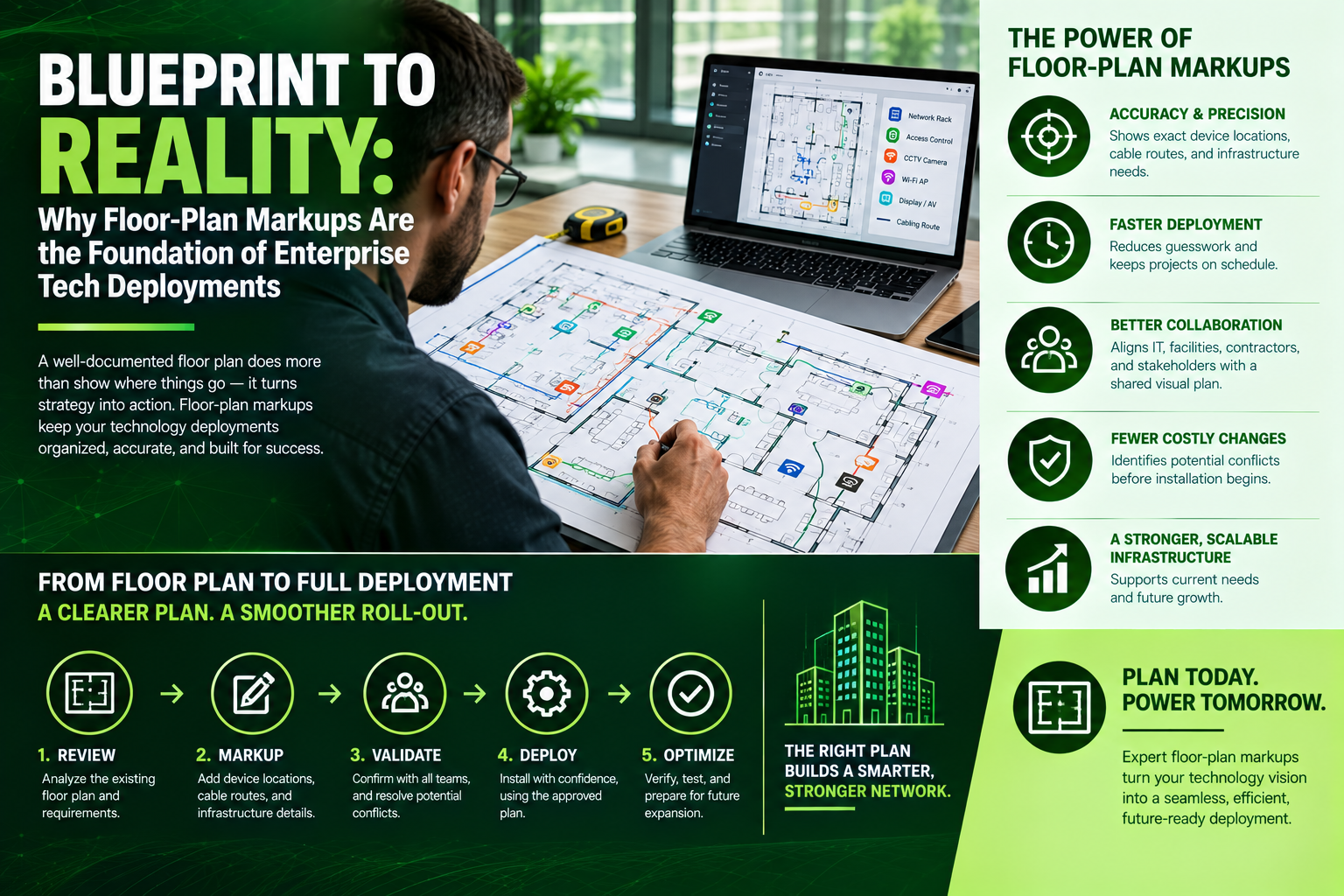
Blueprint to Reality: Why Floor-Plan Markups Are the Foundation of Enterprise Tech Deployments
Unspooling Ethernet cables without a detailed floor-plan markup is a recipe for dead zones, exceeded length limits, and expensive change orders. Discover how low-voltage architectural markups transform raw blueprints into precise IT roadmaps—and see how Volthound delivers standardized, error-free overlays for seamless technology deployments.
Imagine opening the architectural drawings for a 50,000-square-foot corporate office or industrial warehouse. To the untrained eye, it is a grid of walls, doors, and room dimensions. But to a network engineer, low-voltage technician, or security architect, that blueprint represents a dynamic map of radio frequency signals, electrical loads, and physical cable routes.
Before a single reel of Ethernet cable is unspooled or a security camera is mounted, high-performing IT teams rely on Floor-Plan Markups (also referred to as low-voltage architectural overlays or takeoff markups).
Without precise markup overlays, digital blueprints remain purely theoretical—frequently leading to misallocated access points, exceeded cable length limits, poor camera sightlines, and costly mid-construction change orders.
What Are Floor-Plan Markups?
A floor-plan markup is a detailed graphical layer superimposed onto a facility's architectural CAD file or vector PDF floor plan. It translates technical low-voltage specifications into a standardized visual language, defining exact physical hardware placements, underlying cable pathways, and environmental boundaries.
Instead of leaving equipment placement to educated guesses on installation day, every project stakeholder—from electricians and general contractors to network engineers and facility managers—operates from a single visual source of truth.
Key Pillars of a Modern Floor-Plan Markup
Rather than relying on vague notes, a comprehensive floor-plan markup visualizes the infrastructure across four core layers:
1. Device Drop Mapping
This layer assigns exact symbol placements for every endpoint in the facility. It maps single and dual data drops for desktop workstations, IP phones, and networked printers. For ceiling-mounted infrastructure, it designates spatial positioning for wireless access points (WAPs), VoIP speakers, ceiling microphone arrays, and environmental sensors. For security infrastructure, it details lens orientations for IP surveillance cameras, access control card readers, door strikes, and request-to-exit (REX) sensors.
2. Telecommunications & Equipment Room Layouts
Beyond general office space, markups detail the nerve centers of the network: the Main Distribution Frame (MDF) and Intermediate Distribution Frames (IDFs). This includes server rack positioning, patch panel layouts, dedicated power outlet requirements (such as NEMA locking connectors), backup UPS placements, and dedicated HVAC cooling clearance to prevent equipment overheating.
3. Cable Pathways and Riser Routing
Cables cannot simply take the shortest path through a building. Markups outline designated pathways using cable trays, ceiling J-hooks, floor trenches, and vertical riser shafts between floors. This visual guidance ensures that data cabling stays clear of high-voltage electrical lines that cause electromagnetic interference (EMI) and stays within fire-rated plenum ceiling spaces.
4. Environmental & Coverage Boundaries
Advanced digital markups incorporate environmental context. They visualize wall construction types (such as drywall, concrete, or glass) and map theoretical or measured coverage zones for Wi-Fi access points and motion sensors, ensuring no dead zones remain once construction finishes.
Why Floor-Plan Markups Are Critical for Enterprise IT
Eliminating Costly Change Orders: Moving a data drop or re-coring a concrete wall mid-construction costs significantly more than updating a digital mark on a blueprint. Markups flag physical obstacles and spatial conflicts long before technicians arrive on site.
Enforcing Standards & Distance Limits: Standard copper Ethernet runs (Cat6/Cat6A) have a strict maximum channel distance limit of 100 meters (328 feet). Floor-plan markups calculate exact path lengths from the MDF or IDF rooms to ensure runs never exceed performance thresholds.
Optimizing Hardware Sightlines & Signals: Markups define camera lens angles to eliminate blind spots around physical obstructions while mapping wireless coverage around signal-absorbing barriers like concrete pillars or low-E glass.
Streamlining Multi-Trade Coordination: General contractors, electricians, HVAC technicians, and low-voltage installers use markups to coordinate ceiling space, preventing cable trays from conflicting with ductwork or lighting grid fixtures.
How Volthound Empowers Clients with Precision Markups
Translating complex engineering standards into actionable visual blueprints requires technical precision and deep field experience. Volthound combines advanced site surveying technology with low-voltage engineering expertise to deliver end-to-end floor-plan markups for enterprise projects.
Here is how Volthound optimizes floor-plan markups for their clients:
Interactive Digital CAD & PDF Overlays: Volthound transforms raw architectural drawings into standardized digital markups, detailing every data drop, camera placement, and cable pathway with exact measurements and clear symbol keys.
Predictive Heatmapping & Coverage Surveys: Using advanced modeling tools, Volthound overlays wireless signal propagation directly onto your floor plan, identifying dead zones, wall attenuation, and optimal access point density prior to installation.
Cross-Trade & Code Compliance Review: Volthound collaborates directly with architects, general contractors, and IT leaders to ensure all cable pathways comply with local building codes, plenum fire standards, and structural load limits.
As-Built Documentation Handoff: Upon project completion, Volthound provides updated "As-Built" floor-plan markups reflecting final cable routes, labeled patch panel terminations, and port IDs. This gives your internal IT team a permanent, clear roadmap for ongoing maintenance and future expansion.
Silence on the Line? How to Master Audio-Visual (AV) Troubleshooting Before Your Next Big Pitch
Black screens, loud feedback, and frozen video calls can ruin critical meetings in seconds. Uncover the root causes behind common audio-visual glitches—from hidden cable failures to network bottlenecks—and see how Volthound builds and maintains reliable, high-performance AV systems for modern businesses.
Few workplace situations provoke panic quite like an audio-visual failure.
You stand in front of a board of executives or an eager client, hit "Share Screen" or turn on the microphone, and... nothing. The display remains black, the audio emits a high-pitched screech, or the video drops frames like a buffering clip from 2005.
In modern hybrid workplaces, boardrooms, and event spaces, AV failure isn't just an inconvenience—it halts productivity, damages brand credibility, and wastes billable hours.
Understanding how to systematically diagnose AV failures—and knowing when to rely on experts—is the key to seamless digital experiences.
The 4 Most Common AV Failures (And Quick Fixes)
1. "No Signal" on the Main Display
The Culprit: Loose cabling, incorrect input selection, or handshake failures (HDCP/EDID compatibility between the display and source).
Quick Check: Confirm the display's input channel matches the physical port in use (HDMI 1 vs. HDMI 2). If using a laptop, press Win + P (Windows) or adjust System Settings > Displays (Mac) to ensure output mirror/extension is activated.
2. Muted Audio or Harsh Feedback
The Culprit: Incorrect system output routing, unpowered active speakers, or microphone gain staged too high.
Quick Check: Verify the operating system's sound settings haven't defaulted to an internal laptop speaker. If hearing an echo or squeal during a video call, ensure the physical microphone isn't positioned directly in front of an active speaker output.
3. Choppy Video or Lagging Streaming
The Culprit: Bandwidth throttling, poor network cabling, or overburdened video processing hardware.
Quick Check: Reduce screen-share resolution from 4K to 1080p within your conferencing software to lower processing load. If connected via Wi-Fi, switch to a dedicated wired Ethernet drop.
4. Touch Panels or Smart Control Systems Unresponsive
The Culprit: Network communication loss between the control processor, IP-controlled hardware, and the user interface.
Quick Check: Power-cycle the control interface or verify PoE (Power over Ethernet) power delivery to the wall mount or tabletop unit.
Root Causes: Why AV Systems Really Fail
While simple issues can be resolved with a reboot or a cable swap, recurring AV glitches point to deeper underlying infrastructure flaws:
Unmanaged Cable Infrastructure: Damaged cable runs inside walls or under floor boxes introduce intermittent signal loss.
Poor Network Integration: Modern AV systems rely heavily on AV-over-IP (AVoIP). Without proper VLAN segmentation and network switch configurations, video and audio streams suffer packet loss.
Outdated Firmware & Driver Mismatches: Disconnects between BYOD (Bring Your Own Device) operating systems and room hardware create software conflicts.
How Volthound Solves Your AV and Media Infrastructure Challenges
When critical communication environments—such as corporate conference rooms, control centers, auditorium spaces, and training facilities—demand absolute reliability, Volthound provides turnkey technical support and infrastructure management.
Here is how Volthound eliminates AV friction for enterprise clients:
Complete AV Infrastructure Audits: Volthound engineers inspect, trace, and test every signal path—from source devices and matrix switchers to displays and speakers—identifying hidden hardware bottlenecks and cable degradation before catastrophic failures occur.
AV-over-IP & Network Optimization: Because high-definition AV depends on robust networking, Volthound configures dedicated switches, subnetting, and Quality of Service (QoS) protocols so video and audio streams never contend for bandwidth with general data traffic.
Rack Cleanup & Signal Management: Volthound transforms disorganized, unlabelled equipment racks into streamlined, color-coded systems with heat dissipation management, ensuring control units and amplifiers operate under safe thermal conditions.
Proactive Maintenance & Emergency Support: Volthound delivers structured preventive maintenance schedules, firmware validation, and rapid technical response to ensure your meeting rooms remain operational 24/7.

Before You Build, Survey: Why Technology Site Surveys Are the Bedrock of Modern IT Infrastructure
Skipping a technology site survey can derail your entire IT rollout before it starts. From unmanageable power requirements to hidden cable obstacles, discover why site surveys are the essential bedrock of modern network infrastructure—and how Volthound delivers precise, full-spectrum site audits for seamless technology deployments.
Picture this: your company invests tens of thousands of dollars into an enterprise tech rollout—upgraded servers, high-density Wi-Fi 6 access points, unified security cameras, and VoIP infrastructure.
Opening day arrives, and chaos unfolds. Power outlets are out of reach, concrete pillars block critical signal paths, server racks run out of physical space, and network drops stop several feet short of where equipment needs to sit.
This costly operational breakdown stems from a common mistake: skipping the Technology Site Survey.
A Technology Site Survey bridges the gap between digital architectural blueprints and physical real-world environments, ensuring your infrastructure works seamlessly on day one.
What Is a Technology Site Survey?
A Technology Site Survey (TSS) is an exhaustive on-site and digital inspection of a facility's physical, electrical, spatial, and environmental conditions. It determines whether a building can support planned IT deployments, network upgrades, or new hardware implementations.
Instead of guessing cabling pathways, mounting points, power requirements, or environmental factors, engineers gather empirical data to build an accurate technical blueprint before any hardware is purchased or installed.
Key Pillars of a Comprehensive Tech Survey
Spatial & Environmental Inspection: Evaluates server room rack space, floor weight tolerances, cooling capacity (BTUs/HVAC), and physical mounting surfaces.
Power & Electrical Audit: Verifies main panel capacities, dedicated breaker availability, back-up UPS capabilities, and outlet placements.
RF & Wireless Spectrum Analysis: Identifies physical barriers (concrete, low-E glass, structural steel) and radio frequency interference that disrupt Wi-Fi, cellular, or IoT signals.
Cabling & Pathway Mapping: Determines optimal pathways through conduit, drop ceilings, and cable trays while ensuring runs stay within strict distance limits (e.g., 90m for Cat6A).
How Volthound Delivers Flawless Site Surveys
Executing a successful site survey requires expertise across electrical engineering, structured cabling, wireless dynamics, and physical security. Volthound provides end-to-end technology site surveys tailored to commercial, industrial, and enterprise environments:
3D Virtual & On-Site Mapping: Volthound engineers combine predictive software modeling with rigorous physical walkthroughs to map your space with pin-point accuracy.
Spectrum & RF Diagnostics: Using specialized spectrum analyzers, Volthound identifies dead zones, attenuation sources, and co-channel interference before mounting a single access point.
Infrastructure Capacity Audits: Volthound evaluates your existing rack space, patch panels, power draw, and thermal load to prevent equipment failure or unexpected expansion costs.
Detailed Scope of Work (SOW) & Schematic Handoff: You receive a complete CAD/digital schematic detailing precise drop locations, AP placements, cable runs, bill of materials (BOM), and cost forecasts.